Novel high-voltage SF6 self-energy blowing-assisted circuit breaker arc extinguish chamber

A circuit breaker, SF6 technology, applied in high-voltage air circuit breakers, high-voltage/high-current switches, circuits, etc., can solve problems such as reducing the reliability of breaking short-circuit current, high post-arcing temperature between contacts, and affecting medium recovery speed. , to achieve the effect of being conducive to arc extinguishing, short arcing time, and improving work reliability

Pending Publication Date: 2021-11-02
SHENYANG POLYTECHNIC UNIV +2
View PDF0 Cites 0 Cited by
  • Summary
  • Abstract
  • Description
  • Claims
  • Application Information

AI Technical Summary

Problems solved by technology

[0003] However, the self-energy circuit breaker still has the risk of breaking failure when breaking the current. There are many factors affecting the breaking failure, such as the small arc blowing area at the nozzle, slow energy dissipation, poor heat dissipation between contacts, and the influence of valve vibration The pressure in the expansion chamber is established, which in turn affects the gas flow velocity during arc blowing, etc., which may lead to high after-arc temperature between contacts and affect the recovery speed of the medium, resulting in post-arc thermal breakdown or electrical breakdown, and then the arc reignites and breaks Fail, lower SF 6 Reliability of breaking short-circuit current of self-energy circuit breaker

Method used


Image

  • Novel high-voltage SF6 self-energy blowing-assisted circuit breaker arc extinguish chamber
  • Novel high-voltage SF6 self-energy blowing-assisted circuit breaker arc extinguish chamber
  • Novel high-voltage SF6 self-energy blowing-assisted circuit breaker arc extinguish chamber

Examples


Embodiment Construction

[0023] The specific implementation manners of the present invention will be further described in detail below in conjunction with the accompanying drawings and embodiments. The following examples are used to illustrate the present invention, but are not intended to limit the scope of the present invention.

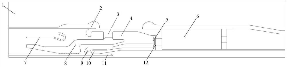
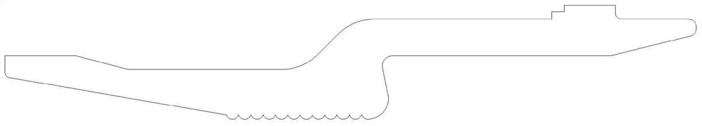
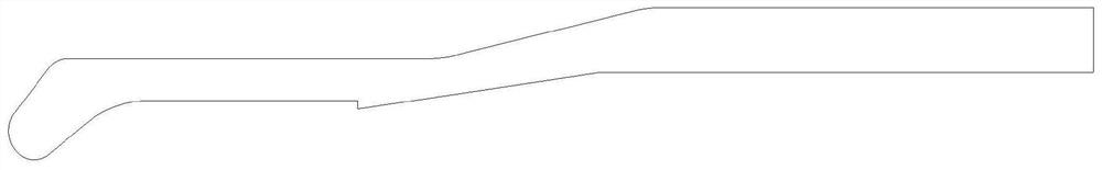
[0024] In this example, the high pressure SF 6 Self-energy blown circuit breaker arc extinguishing chamber such as figure 1 shown, including SF 6 Gas zone 1, static main contact 2, moving main contact 3, expansion chamber 4, one-way valve 5, pressure cylinder 6, shield cover 7, large nozzle 8, small nozzle 9, moving arc contact 10 and static arc contact head; a novel high pressure SF of the present invention 6 On the basis of the existing arc extinguishing chamber structure, the self-energy-assisted blowing type circuit breaker arc extinguishing chamber modifies the large nozzle, small nozzle, static arc contact and one-way valve as follows figure 2 Large spout with r...


PUM


Abstract

The invention provides a novel high-voltage SF6 self-energy blowing-assisted circuit breaker arc extinguish chamber, which relates to the technical field of power transmission and transformation equipment. According to the novel high-voltage SF6 self-energy blowing-assisted circuit breaker arc extinguish chamber, on the basis of an existing arc extinguish chamber structure, a large nozzle, a small nozzle, a static arc contact and a one-way valve are modified into the large nozzle with a throat protrusion, an improved small nozzle structure, the static arc contact with a hollow structure and the one-way valve with a spring positioning ball; a plurality of corrugated bulges are arranged at the throat part of the large nozzle, so that a gap between the large nozzle and the static arc contact is reduced; according to the one-way valve with the spring positioning bead position, a plurality of spring positioning beads are arranged in an expansion chamber and an air cylinder channel, the length of the one-way valve is increased, the one-way valve is slotted, and the spring positioning beads slide into the slotted position of the one-way valve to lock the one-way valve after the one-way valve is closed, so that the one-way valve is prevented from being opened after being closed. The arc extinguish chamber increases the utilization rate of arc energy, improves the arc blowing effect of the arc root of the arc at the front end of the contact, and enhances the arc extinguishing capability of the circuit breaker.

Description

technical field [0001] The invention relates to the technical field of power transmission and transformation equipment, in particular to a new high-voltage SF 6 Self-help blowing type circuit breaker arc extinguishing chamber. Background technique [0002] Compressed air SF 6 Circuit breakers occupy a dominant position in the high-voltage switch market due to their excellent breaking performance and insulation performance. Since the compressed air circuit breaker needs the cylinder to continue to do work on the gas in the cylinder during the breaking process, especially for the UHV switchgear, it needs to be equipped with a high-power operating mechanism to complete the breaking task, which poses a problem for the reliability of the high-voltage switchgear. higher requirements. while SF 6 The self-energy circuit breaker can make up for this deficiency by virtue of its small size and low operating power. High pressure SF 6 The self-energy circuit breaker uses the energy...

Claims


Application Information

Patent Timeline
Patent Type & Authority Applications(China)
IPC IPC(8): H01H33/08H01H33/86H01H33/72H01H1/62
Inventor 林莘张博徐建源谭盛武钟建英段晓辉庚振新林一泓宋宇魏登峰张佳
Owner SHENYANG POLYTECHNIC UNIV
Why Eureka
Try Eureka