Cylindrical cabin section wallboard structure simulation static test device and method

A static test and plate structure technology, applied in the field of aerospace mechanics testing, can solve problems such as over-examination of cabin structure, under-examination of panel structure, distortion of force transmission path, etc.

Active Publication Date: 2021-11-02
BEIJING RES INST OF SPATIAL MECHANICAL & ELECTRICAL TECH
View PDF6 Cites 5 Cited by
  • Summary
  • Abstract
  • Description
  • Claims
  • Application Information

AI Technical Summary

Problems solved by technology

Under the same load conditions, different design forms of tooling and simulation devices lead to distortion of the force transmission path, resulting in partial over-examination of the cabin structure or under-examination of the panel structure. To ensure the load-bearing assessment of the inner panel structure of the cylindrical cabin, it is necessary to use High reliability and precision simulation device for static test
[0004] In the prior art, there is no simulation device specially used for the static test of the cylindrical cabin panel structure. Usually, the real panel structure is used for the test, so the processing cycle and cost usually cannot meet the test requirements. Therefore, it is necessary to design In consideration of various aspects such as processing, materials, etc., a static test simulator suitable for the columnar cabin panel structure is designed to simulate the load-bearing assessment of the columnar cabin panel structure in the static test

Method used


Image

  • Cylindrical cabin section wallboard structure simulation static test device and method
  • Cylindrical cabin section wallboard structure simulation static test device and method
  • Cylindrical cabin section wallboard structure simulation static test device and method

Examples


Embodiment Construction

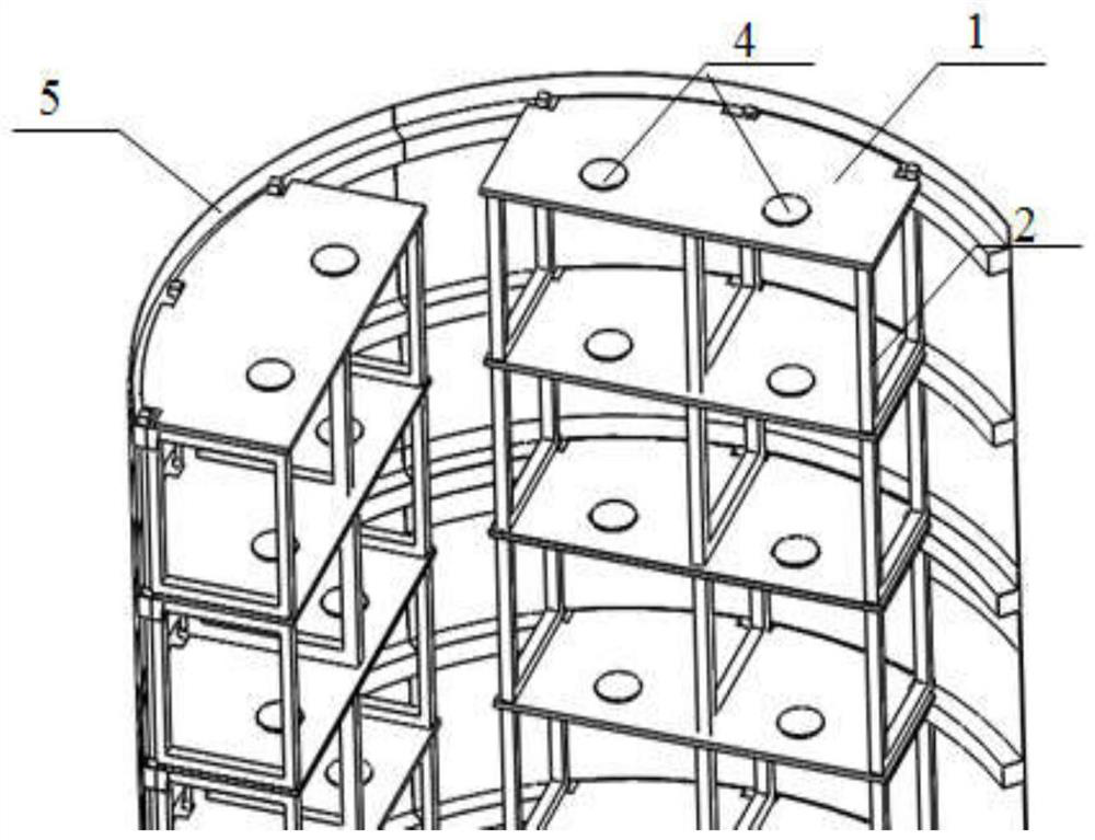
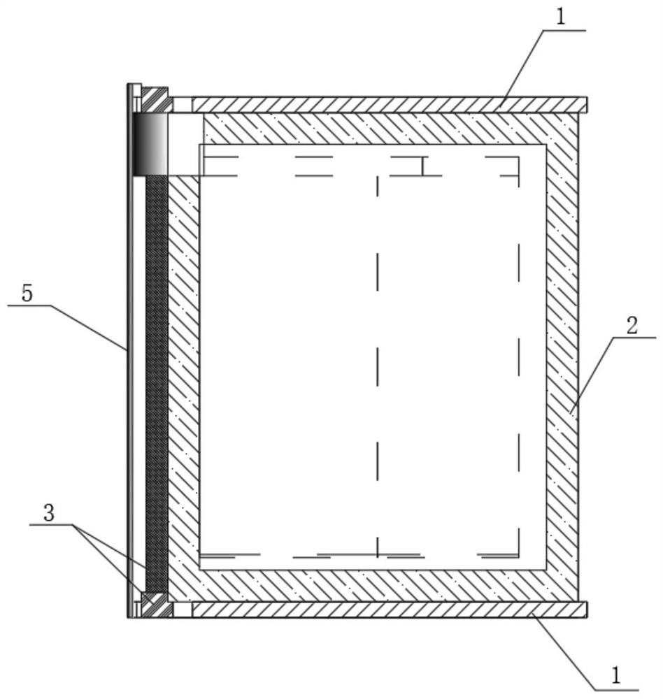
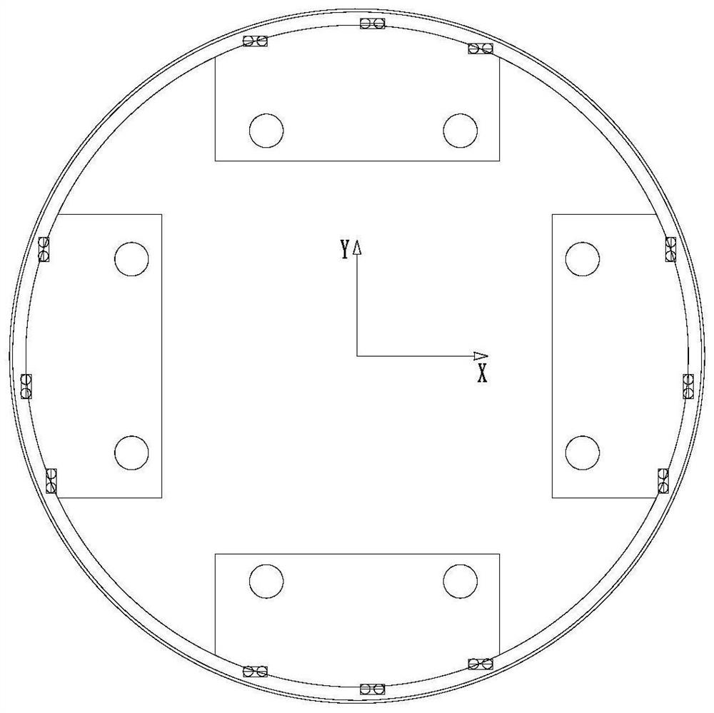
[0022] combine Figure 1 to Figure 4 As shown, a specific implementation of the simulated static test device and method for a columnar cabin wall plate structure provided by the present invention will be described.

[0023] A static test device for simulating a cylindrical cabin wall plate structure, comprising a horizontal plate 1 , a vertical frame 2 , a bulkhead connection structure 3 and a loading mounting seat 4 . The test device is used in the static test process of the wall plate structure of the cylindrical cabin section. The distortion of the force transmission path of the wall plate structure simulation device of the cylindrical cabin section has an adverse effect on the accuracy of the test assessment. The device can be used to simulate the main structure of the entire cabin section The test device meets the strength and stiffness requirements of the main structure and local structure of the entire cabin, and can also simulate the longitudinal and transverse force m...


PUM


Abstract

The invention provides a cylindrical cabin section wallboard structure simulation static test device and method, and relates to the technical field of aerospace mechanics testing. The device comprises a horizontal plate, a vertical frame, a cabin wall connecting structure and a loading mounting seat, the horizontal plate simulates a mounting plate structure in a cabin body, the horizontal plate is mounted on a cylindrical cabin section wall plate structure, and the cabin wall connecting structure comprises an adapter block and a connecting beam and simulates longitudinal and transverse force transmission structures in the cabin body. The vertical frame is fixedly connected with the horizontal plate and the bulkhead connecting structure to simulate the longitudinal bearing of a bulkhead wall plate structure, and the loading mounting seat is fixed on the horizontal plate or the vertical frame to simulate the actual bearing position of a cylindrical bulkhead section wall plate structure and the mounting of longitudinal and transverse loading devices. The device is used for carrying out the static test on the cylindrical cabin wall plate structure, simulating the bearing and force transmission paths of the structure, and simulating the transverse and longitudinal loads of the cabin wall plate structure, so that the test precision is improved, and the reliability and scientificity of the test structure are ensured.

Description

technical field [0001] The invention relates to the technical field of aerospace mechanics testing, in particular to a static test device and method for simulating a wall plate structure of a cylindrical cabin section. Background technique [0002] Cargo spacecraft, space stations and other large spacecraft are mostly cylindrical cabins, and the cargo warehouses or instrument cabins inside the cylindrical cabins are all made of multi-layer wall panels. In order to ensure the structural reliability and stability of the spacecraft during use, the structural design of its bearing capacity is the primary goal. In the development process, it is necessary to simulate the load-bearing form of the spacecraft under laboratory conditions, and to assess and verify its structure. [0003] During the static test, due to the limitations of the internal space of the cylindrical cabin and the conditions of the test simulator, the static test and the actual load-bearing form of the cylindri...

Claims


Application Information

Patent Timeline
Patent Type & Authority Applications(China)
IPC IPC(8): G01M13/00
CPCG01M13/00Y02T90/00
Inventor 臧博刘炳立张宝康刘禹含邢立明
Owner BEIJING RES INST OF SPATIAL MECHANICAL & ELECTRICAL TECH
Why Eureka
Try Eureka