Guide control device and rotary guide drilling tool
A technology of steering control and control rod, applied in directional drilling, photovoltaic power generation, etc., can solve the problems of complex control process, and achieve the effect of high control accuracy and simple operation process
- Summary
- Abstract
- Description
- Claims
- Application Information
AI Technical Summary
Problems solved by technology
Method used
Image

Examples
Embodiment 1
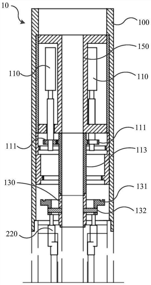
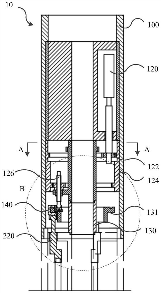
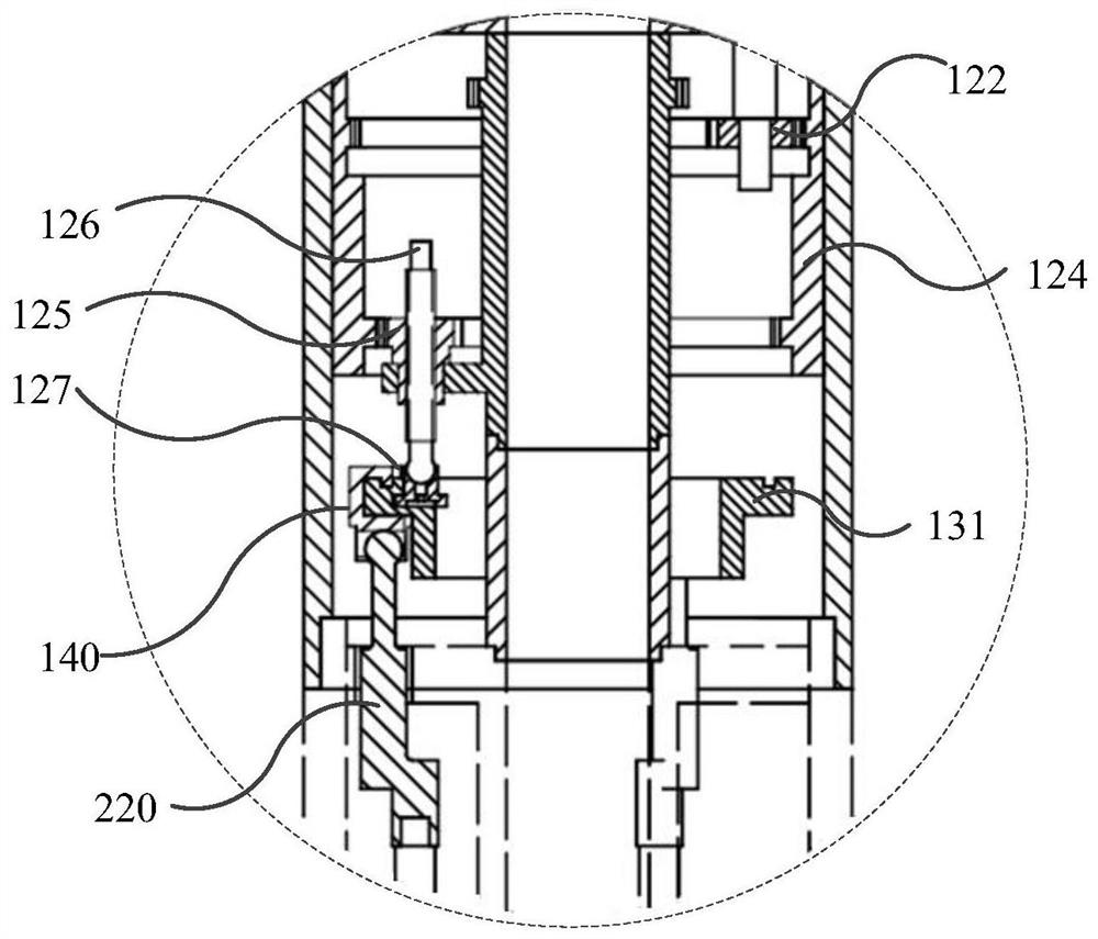
[0052] figure 1 A front view of a guidance control device provided for a possible embodiment of the present invention; figure 2 Another perspective front view of the guide control device provided for a possible embodiment of the present invention; image 3 for figure 2 Enlarged view of B; Figure 4 for figure 2 A-A sectional view of ; Figure 5 for figure 1 Schematic diagram of the structure of the fourth spur internal gear; Image 6 for figure 1 Schematic diagram of the structure at the center adjustment panel; Figure 7 for figure 1 Schematic diagram of the movable plate in the middle; Figure 8 for figure 1 Schematic diagram of the structure of the mid-slip shoe; Figure 9 for figure 1 Schematic diagram of another angle structure at the center adjustment disc; Figure 10 for figure 1 Schematic diagram of the structure of the sliding joint; Figure 11 for figure 1 Schematic diagram of the structure of the control rod.
[0053] refer to Figure 1-Figure 1...
Embodiment approach
[0074] In a further possible implementation, the azimuth adjustment mechanism includes an azimuth drive member 110 and an azimuth transmission assembly, the azimuth transmission assembly is connected between the shaft sleeve 130 and the azimuth drive member, and the azimuth drive member drives the shaft sleeve 130 to rotate through the azimuth transmission assembly; the inclination angle The adjustment mechanism includes an inclination driving member 120 and an inclination transmission assembly, the inclination transmission assembly is connected between the movable disk 131 and the inclination driving member 120, and the inclination driving member 120 drives the movable disk 131 to swing through the inclination transmission assembly.
[0075] The azimuth adjustment mechanism and the inclination adjustment mechanism are provided with their own driving parts and transmission components to achieve their own independent control, which is convenient for separate manipulation, and the...
Embodiment 2
[0095] Figure 12 A front view of a rotary steerable drilling tool provided for another possible embodiment of the present invention.
[0096] refer to Figure 12 As shown, another possible embodiment of the present invention provides a rotary steering drilling tool 20, including a second housing 200, a control rod 220, a valve core wedge 232, a drill bit guiding tool 240 and the above-mentioned steering control device 10, The second housing 200 is open at both ends and is hollow. The second housing 200 supports the second end of the first housing 100 connected to the guiding control device 10 .
[0097] The second housing 200 is provided with a support ring 210 close to the first housing 100. The support ring 210 supports and connects the shaft sleeve 130 of the guide control device 10 through bearings, and the support ring 210 is provided with a control hole, and a control rod is inserted in the control hole. 220 , the first end of the control rod 220 is connected to the s...
PUM
 Abstract
Description
Claims
Application Information
 - R&D
- Intellectual Property
- Life Sciences
- Materials
- Tech Scout
- Unparalleled Data Quality
- Higher Quality Content
- 60% Fewer Hallucinations
Browse by: Latest US Patents, China's latest patents, Technical Efficacy Thesaurus, Application Domain, Technology Topic, Popular Technical Reports.
© 2025 PatSnap. All rights reserved.Legal|Privacy policy|Modern Slavery Act Transparency Statement|Sitemap|About US| Contact US: help@patsnap.com