
Circulating liquid cooling method for flexible circuit board

A flexible circuit board and circulating fluid technology, which is applied in the direction of modification using liquid cooling, modification of cooling/ventilation/heating, modification by conduction heat transfer, etc. problem, to achieve a good cooling effect

Inactive Publication Date: 2021-10-29
深圳市征阳电路科技有限公司
View PDF0 Cites 0 Cited by
  • Summary
  • Abstract
  • Description
  • Claims
  • Application Information

AI Technical Summary

Problems solved by technology

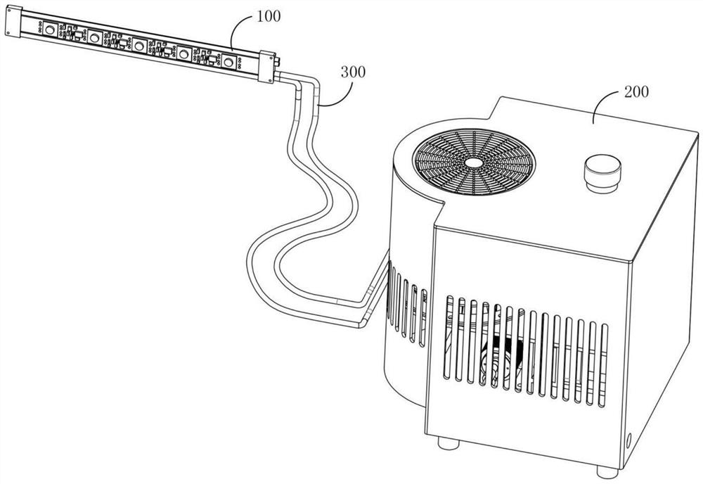
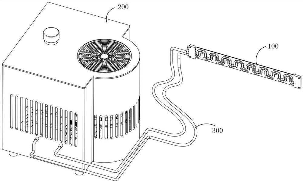
[0002] Flexible circuit boards, also known as "soft boards", are printed circuits made of flexible insulating substrates, which can meet the design needs of smaller and higher-density installations, and also help reduce assembly processes and enhance reliability. Flexible circuit boards Widely used in electronic products, but during the use of flexible circuit boards, the previous flexible circuit boards have serious heat generation during use, and it is easy to cause heat to not dissipate in sealed equipment, resulting in excessive temperature of the circuit board working environment , leading to circuit boards prone to problems and also affecting the working life of flexible circuit boards. Therefore, it is necessary for the present invention to propose a circulating liquid cooling method for flexible circuit boards. The cooling liquid for cooling the flexible circuit board is always kept at a low temperature, and the cooling effect is better, and the invention can adapt to flexible circuit boards of different lengths without affecting the cooling of the flexible circuit board by the cooling member

Method used


Image

  • Circulating liquid cooling method for flexible circuit board
  • Circulating liquid cooling method for flexible circuit board
  • Circulating liquid cooling method for flexible circuit board

Examples


Embodiment Construction

[0076] In order to further illustrate the technical means and efficacy of the present invention to achieve predetermined amount of invention, the specific embodiments, structures, features, and efficacy of the present invention will be described in detail below with reference to the accommodation invention.

[0077] A flexible circuit board circulating liquid cooling method, its steps are:

[0078] S1: The reduction motor 510 in the inlet and outlet mechanism 500 operates with the link member 520, so that the plunger pump A530 in the inlet and outlet mechanism 500 is in the suction state, and the plunger pump B540 is in the discharge state, wherein the column of the suction state The plug pump A530 causes the coolant in the reservoir 400 through the connecting pipe A301 in the connecting pipe network 300 into the cooling pipe B113 in the cooling member 100 and the cooling tube A112, while the pumping state The plug pump A530 also enables the coolant 553 that is previously located ...


PUM


Abstract

The invention relates to a circulating liquid cooling method, which comprises the following steps that: S1, cooling liquid in a liquid storage tank flows into a cooling pipe b and a cooling pipe a by a plunger pump a in a suction state, and the cooling liquid which is previously positioned in the cooling pipe b and the cooling pipe a and has increased temperature flows into a pump shell of the plunger pump a; S2, the plunger pump a in the discharging state discharges cooling liquid in a pump shell of the plunger pump a into a cooling tower for cooling, and a plunger pump b in the suction state sucks the cooled cooling liquid in the cooling tower into a pump shell of the plunger pump b; S3, the plunger pump a in the suction state enables the cooling liquid in the liquid storage tank to flow into the cooling pipe b and the cooling pipe a, the cooling liquid which is located in the cooling pipe b and the cooling pipe a previously and has the temperature increased flows into a pump shell of the plunger pump a, and the plunger pump b in the discharging state discharges the cooling liquid in the pump shell of the plunger pump b into the liquid storage tank; and S4, the steps S2-S3 are repeated.

Description

Technical field [0001] The present invention relates to the field of flexible circuit boards, and more particularly to the cooling cooling field of the flexible circuit board. Background technique [0002] The flexible circuit board is also known as * # * soft board * # *, is a printed circuit made of flexible insulating substrate, which can meet the design needs of smaller and higher density installations, but also help to reduce assembly process and enhance reliability. The flexible circuit board is widely used in electronic products, but during use, the conventional flexible circuit board is severe during use, and it is easy to cause heat in the sealed equipment, resulting in work. The ambient temperature is too high, causing a problem with the problem of the circuit board, and it also affects the working life of the work flexible circuit board. Therefore, the present invention is necessary to propose a method of circulating a flexible circuit board cycle liquid cooling method...

Claims


Application Information

Patent Timeline
IPC IPC(8): H05K7/20
CPCH05K7/2029H05K7/20327H05K7/20381H05K7/20509H05K7/20136
Inventor 杨艳渝
Owner 深圳市征阳电路科技有限公司
Learn More