Cable terminal mounting structure in transformer substation

A technology of cable termination and installation structure, applied in cable termination, substation grounding layout, etc., can solve the problems of large floor space, limitation, not very beautiful, etc., and achieve the effect of saving floor space, saving cost and convenient installation.

Pending Publication Date: 2021-10-29
镇江电力设计院有限公司
View PDF0 Cites 0 Cited by
  • Summary
  • Abstract
  • Description
  • Claims
  • Application Information

AI Technical Summary

Problems solved by technology

[0002] At present, the 110kV outgoing lines of most 220kV substations are in the form of overhead, but because the formation of such outgoing lines is affected by factors such as terrain, planning, and existing line layout, it is often restricted, which brings difficulty in construction
[0003] In response to this problem, the main method now is to set up cable terminal towers outside the substation enclosure, and the overhead wires are led out from the frame to the terminal towers and then lowered to the ground. However, new pole towers often need to comply with policy requirements, so approval is difficult, and it occupies a large area and requires a large investment

Method used


Image

  • Cable terminal mounting structure in transformer substation
  • Cable terminal mounting structure in transformer substation
  • Cable terminal mounting structure in transformer substation

Examples


Embodiment Construction

[0021] The present invention will be further illustrated below in conjunction with the accompanying drawings and specific embodiments, and it should be understood that these embodiments are only for illustrating the present invention and are not intended to limit the scope of the present invention.

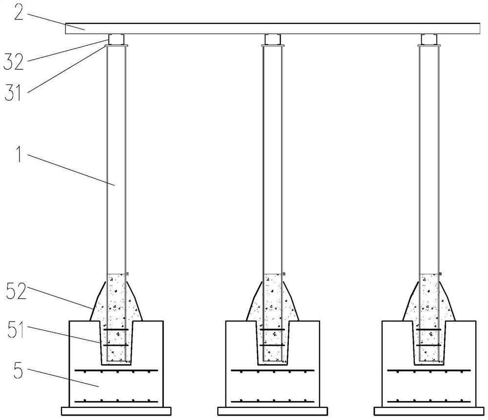
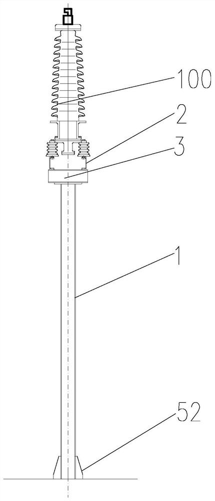
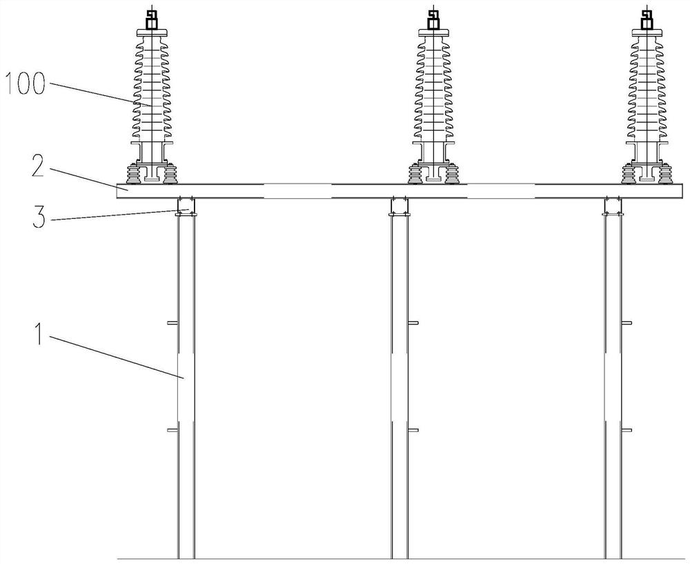
[0022] A cable terminal installation structure in a substation, such as figure 1 As shown originally, it includes column 1, cable installation frame 2, support seat 3, grounding box assembly 4, and base 5.

[0023] Columns 1 are vertically provided with a plurality of columns arranged in a line at intervals in turn. A base 5 is provided at the bottom of each column 1, and a blind hole 51 is provided on the top of the base 5 along its vertical downward direction. The bottom of the column 1 It is inserted into the blind hole 51 to be fixed and fastened to the base 5 through the reinforcing rib 52 . During installation, the base 5 is buried in the ground so that the height of the co...


PUM


Abstract

The invention relates to a cable terminal mounting structure in a transformer substation. The cable terminal mounting structure disclosed by the present invention comprises stand columns, a cable mounting rack, supporting seats and a grounding box assembly, the multiple stand columns are vertically arranged and are sequentially arranged in a straight line at intervals; the cable mounting rack is horizontally placed and stretches across the multiple stand columns; the top end of each stand column is connected with the bottom face of the cable mounting rack through the supporting seat; a plurality of cable terminals are installed on the upper surface of the cable mounting rack at intervals; the bottom ends of the stand columns are fixed to the ground; and the grounding box assembly is installed on the peripheral face of one stand column. According to the cable terminal mounting structure in the transformer substation, the support is additionally arranged at the position, close to an enclosing wall, of the outgoing line framework of a transformer substation to replace a cable terminal tower, so that the occupied area is effectively saved, and the support is compact in structure, small in size, convenient to install, capable of effectively saving cost, safe and attractive and conforms to the environment-friendly and resource-saving concept of the State Grid.

Description

technical field [0001] The invention relates to the field of power transmission line equipment, in particular to a cable terminal installation structure in a substation. Background technique [0002] At present, most of the 110kV outgoing lines of 220kV substations are in the form of overhead, but because the formation of such outgoing lines is affected by factors such as terrain, planning, and existing line layout, it is often restricted, which brings difficulty in construction. [0003] In response to this problem, the main method now is to set up cable terminal towers outside the substation enclosure, and the overhead wires are led out from the frame to the terminal towers and then lowered to the ground. However, new towers often need to meet the policy requirements, so the approval is difficult, and it occupies a large area and requires a large investment. Contents of the invention [0004] Purpose of the invention: In view of the above problems, the purpose of the pr...

Claims


Application Information

Patent Timeline
Patent Type & Authority Applications(China)
IPC IPC(8): H02G15/06H02B5/01
CPCH02G15/06H02B5/01
Inventor 温祥华姚斐周国雨高皋
Owner 镇江电力设计院有限公司
Why Eureka
Try Eureka