Laser remote control switch system

A remote control switch and laser technology, applied in the field of laser remote control switch system, can solve the problems of short control distance, long control distance, complex circuit structure, etc., and achieve the effect of simple control circuit, strong anti-interference and large control distance

Active Publication Date: 2021-10-29
TSINGHUA UNIV +1
View PDF21 Cites 0 Cited by
  • Summary
  • Abstract
  • Description
  • Claims
  • Application Information

AI Technical Summary

Problems solved by technology

[0002] Commonly used remote control devices include radio remote control devices and infrared remote control devices. These two types of remote control devices are commonly used in industries such as industrial remote control, home appliance remote control, and toy remote control. The advantage of wireless remote control switches is that the control distance is long and the control distance can reach More than tens of meters, the disadvantage is that when the carrier frequency is the same, it may interfere with other remote control devices and other electrical appliances, and the transmitter signal needs to be modulated, and the receiver needs demodulation circuits and amplifier circuits, so the circuit structure is more complicated; the advantages of infrared remote control switches The interference is small, generally only a few meters of remote control distance, infrared rays generally cannot pass through walls, and do not interfere with receiving devices in other rooms. The disadvantage is that the control distance is not far, and there are also dozens of meters, but the cost is high. At the same time, the power consumption is also large, and the transmitted signal needs to be modulated, and the receiver needs to be demodulated and amplified before it can be used.

Method used


Image

  • Laser remote control switch system
  • Laser remote control switch system
  • Laser remote control switch system

Examples


Embodiment Construction

[0041] The nanofiber actuator provided by the present invention, the actuation system using the actuator and other applications will be described in detail below with reference to the accompanying drawings.

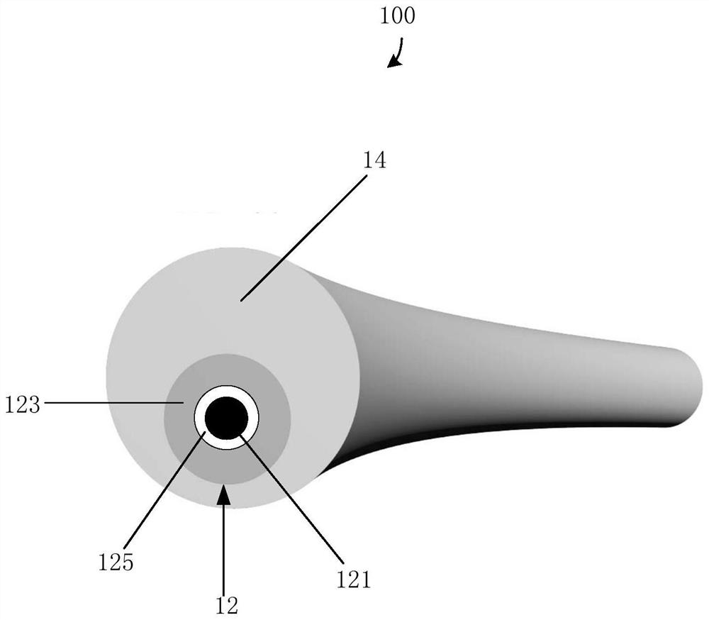
[0042] See figure 1 , the first embodiment of the present invention provides a nanofiber actuator 100 , which includes a composite structure 12 and a vanadium dioxide layer 14 . The composite structure 12 includes a carbon nanotube wire 121 and an aluminum oxide layer 123, the aluminum oxide layer 123 is coated on the surface of the carbon nanotube wire 121 and arranged coaxially with the carbon nanotube wire 121, the The vanadium dioxide layer 14 is coated on the surface of the composite structure 12 , and the vanadium dioxide layer 14 and the composite structure 12 are arranged non-coaxially.

[0043] The composite structure 12 includes the carbon nanotube wire 121 and the aluminum oxide layer 123 . The composite structure 12 may only consist of the carbon nanotube wi...


PUM

PropertyMeasurementUnit
lengthaaaaaaaaaa
lengthaaaaaaaaaa
diameteraaaaaaaaaa

Abstract

The invention relates to a laser remote control switch system which comprises a laser source and a control circuit, the control circuit comprises a power supply, an electronic device, a first electrode, a second electrode and a photosensitive element, and the power supply, the electronic device, the first electrode, the photosensitive element and the second electrode are electrically connected in sequence to form a loop. The light-sensitive element comprises two nano-fiber actuators, the two nano-fiber actuators bend and actuate along with the change of the temperature to enable the control circuit to be switched off or switched on, each nano-fiber actuator comprises a composite structure body and a vanadium dioxide layer, the composite structure body comprises a carbon nano-tube wire and an aluminum oxide layer; the aluminum oxide layer coats the surface of the carbon nanotube line and is coaxially arranged with the carbon nanotube line, the vanadium dioxide layer coats the surface of the composite structure body, and the vanadium dioxide layer and the composite structure body are not coaxially arranged.

Description

technical field [0001] The invention relates to a laser remote control switch system. Background technique [0002] Commonly used remote control devices include radio remote control devices and infrared remote control devices. These two types of remote control devices are commonly used in industries such as industrial remote control, home appliance remote control, and toy remote control. The advantage of wireless remote control switches is that the control distance is long and the control distance can reach More than tens of meters, the disadvantage is that when the carrier frequency is the same, it may interfere with other remote control devices and other electrical appliances, and the transmitter signal needs to be modulated, and the receiver needs demodulation circuits and amplifier circuits, so the circuit structure is more complicated; the advantages of infrared remote control switches The interference is small, generally only a few meters of remote control distance, in...

Claims


Application Information

Patent Timeline
Patent Type & Authority Applications(China)
IPC IPC(8): G08C23/04
CPCG08C23/04C01B32/168H01H1/0094H01H2061/006H01H61/02H01H2037/326H01H37/46C01B32/158
Inventor 王广马赫金翔原华魏洋李群庆姜开利范守善
Owner TSINGHUA UNIV
Why Eureka
Try Eureka