Eureka AIR delivers breakthrough ideas for toughest innovation challenges, trusted by R&D personnel around the world.

Detection device and control method thereof

A technology of detection device and outgoing direction, applied in measurement devices, radio wave measurement systems, instruments, etc., can solve the problems of increasing the cost and volume of lidar, and achieve the effect of improving resolution

Active Publication Date: 2021-10-29
HUAWEI TECH CO LTD
View PDF15 Cites 4 Cited by
  • Summary
  • Abstract
  • Description
  • Claims
  • Application Information

AI Technical Summary

Problems solved by technology

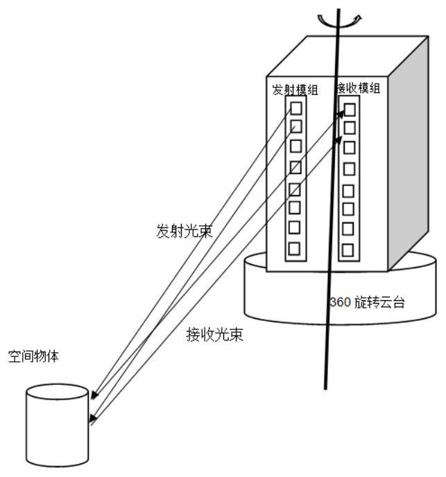
Since the laser radar adopts the point-to-point scanning method, the detectors and laser transmitters need to be set in one-to-one correspondence. If high-precision vertical resolution is to be achieved, the laser transmitters and detectors of the receiving module and the transmitting module need to be added. However, increasing the number of laser emitters and detectors will inevitably increase the cost and volume of the laser radar

Method used


Image

  • Detection device and control method thereof
  • Detection device and control method thereof
  • Detection device and control method thereof

Examples


Embodiment Construction

[0080] The technical solutions in the embodiments of the present application will be described below with reference to the drawings in the embodiments of the present application.

[0081] In the description of this application, the terms "center", "upper", "lower", "front", "rear", "left", "right", "vertical", "horizontal", "top", " The orientation or positional relationship indicated by "bottom", "inner", "outer", etc. is based on the orientation or positional relationship shown in the drawings, and is only for the convenience of describing the application and simplifying the description, rather than indicating or implying the referred device or Elements must have certain orientations, be constructed and operate in certain orientations, and thus should not be construed as limiting the application.

[0082] In the description of this application, it should be noted that unless otherwise specified and limited, the terms "installation", "connection" and "connection" should be un...


PUM


Abstract

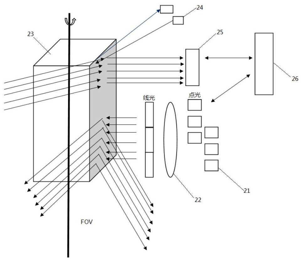
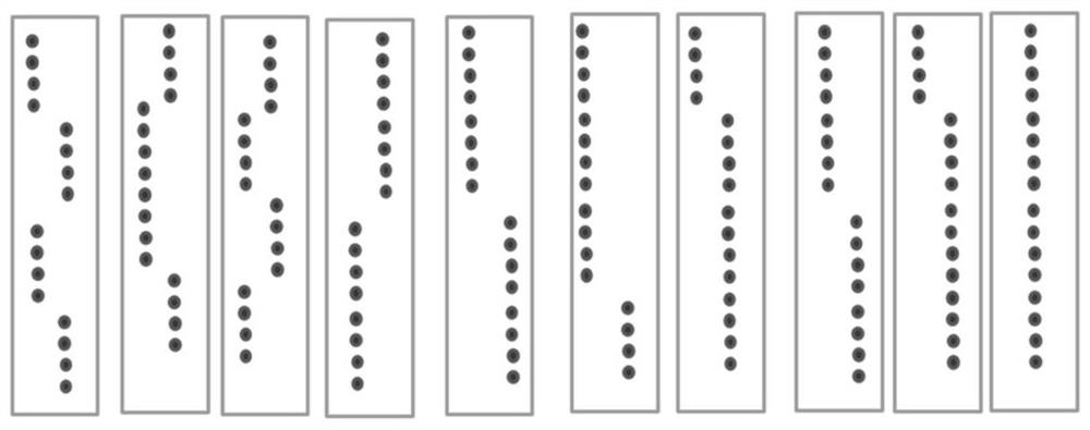
The invention provides a detection device, and the device comprises: a transmitting assembly which is used for transmitting a laser beam; a collimating and shaping assembly which is used for processing the laser beam into a collimated linear laser beam; a scanning rotating mirror assembly which comprises at least one reflecting surface and is used for reflecting the linear laser beam; a receiving assembly which is used for receiving target echoes and converting the target echoes from optical signals into corresponding electric signals, wherein the target echoes comprise reflected signals of the linear laser beams; and a synchronization assembly which is at least used for acquiring the synchronization position of the working reflection surface in the at least one reflection surface, wherein the synchronization position represents the position of the linear laser beam initially received by the working reflection surface, and the working reflection surface corresponds to the emergent direction of the linear laser beam. According to the detection device, the resolution of the detection device can be improved on the basis that the cost and the size of the detection device are not increased.

Description

[0001] This application claims the priority of the Chinese patent application with the application number 202110382166.4 and the application title "a detection device and its control method" filed with the State Intellectual Property Office of China on April 09, 2021, the entire contents of which are incorporated by reference in In this application. technical field [0002] The present application relates to the technical field of laser radar, in particular to a detection device and a control method thereof. Background technique [0003] Lidar technology is an optical measurement technology that measures the distance and other parameters of the target by shining a beam of light, usually a pulsed laser, on the target. For example, lidar measures the distance between a target and a light source by measuring the time difference between emitted light and received light (also known as the time of flight of light). [0004] Lidar output data is called point cloud and has applicat...

Claims


Application Information

Patent Timeline
Patent Type & Authority Applications(China)
IPC IPC(8): G01S7/481G01S17/02
CPCG01S7/4817G01S17/02
Inventor 王曰孟王伟余安亮
Owner HUAWEI TECH CO LTD
Why Eureka
Eureka Blog
Learn More