A Method for Determining Repair Welding Position

A determination method and repair welding technology, applied in welding equipment, measuring devices, auxiliary devices, etc., can solve the problems of inaccurate welding position data, inability to guarantee repair welding position accuracy, low work efficiency, etc., and achieve high accuracy. , High work efficiency, the effect of eliminating relative errors

Active Publication Date: 2021-12-07
四川国芯通智能科技有限公司
View PDF13 Cites 0 Cited by
  • Summary
  • Abstract
  • Description
  • Claims
  • Application Information

AI Technical Summary

Problems solved by technology

However, in this method, the welding position data still needs to be collected and input manually, and the work efficiency is low; and the welding position data may be affected by the position error when the workpiece is fixed, resulting in the inability to correspond accurately after the welding position data is input, and the accuracy of the repair welding position Can not guarantee

Method used


Image

  • A Method for Determining Repair Welding Position

Examples


Embodiment 1

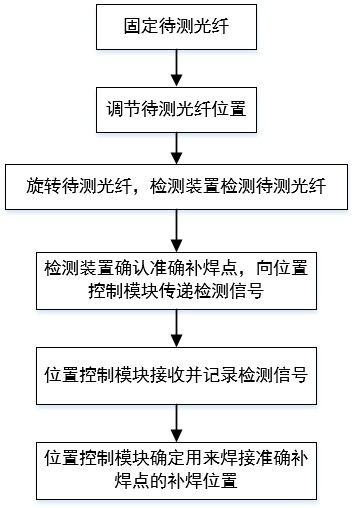
[0031] as attached figure 1 As shown, a method for determining a repair welding position includes the following steps:

[0032] Step 1: Fix the fiber to be tested. In this embodiment, a three-jaw chuck is used to clamp and fix the optical fiber to be tested, and the three-jaw chuck can vertically fix the optical fiber to be tested, which is convenient for rotating the optical fiber to be tested in the subsequent process.

[0033] Step 2: Adjust the up and down displacement of the optical fiber to be tested, so that the detection part of the optical fiber to be tested is aligned with the detection device and the repair welding device; it is convenient for the detection of the detection device and the repair welding of the repair welding device.

[0034] In this embodiment, the detection device is a conventional optical power meter, and the detection part of the optical fiber to be tested is aligned with the detection head of the optical power meter.

[0035] Step 3: Drive the...

Embodiment 2

[0041] A method for determining a repair welding position, comprising the following steps:

[0042] Step 1: Fix the fiber to be tested;

[0043]The optical fiber to be tested in this embodiment is an optical fiber connected to the connector, and the connection method between the connector and the optical fiber is welding; the welding position between the connector and the optical fiber is the position to be detected of the optical fiber to be tested; connection to the fiber. In practical applications, the connection between optical fibers and the connection between optical fibers and other components require connectors to achieve the connection effect, and the tightness of the connection between the connector and the optical fiber will affect the working performance of the optical fiber. Set the welding position as the part to be detected , the welding status can be determined through the detection device in the subsequent steps, and the defects can be remedied in time to avo...


PUM


Abstract

The invention relates to the technical field of repair welding, and discloses a method for determining a repair welding position, comprising the following steps: step 1: fixing the optical fiber to be tested; step 2: adjusting the position of the optical fiber to be tested, so that the position of the optical fiber to be tested is aligned Detection device and repair welding device; Step 3: Drive the optical fiber to be tested to rotate through the adjustment mechanism. When the optical fiber to be tested is rotated, the detection device is always in contact with the part to be detected, and the optical fiber to be tested is detected by the detection device; Step 4: When the detection device detects that the optical fiber to be tested When the measured optical fiber signal changes suddenly, the corresponding contact position between the optical fiber to be tested and the detection device at this time is taken as the accurate repair spot; the detection device transmits the detection signal to the position control module in the adjustment mechanism after determining the correct repair spot; the position control module receives and The detection signal is recorded, and the position control module determines the repair welding position used for welding the repair welding device to accurately repair the welding spot. The method can accurately locate the repair welding position, reduce the error of the repair welding position and improve the overall work efficiency of the repair welding.

Description

technical field [0001] The invention relates to the technical field of repair welding, in particular to a method for determining a repair welding position. Background technique [0002] In order to improve the quality of optical fiber products and save costs, repair welding machines are often used to repair the lack of welding and missing welding of optical fiber products. Repair welding machine refers to the ability to release welding energy in a very small range (less than one square millimeter) in an instant (millisecond level), so that the supplementary material can be completely welded to the workpiece. The overall heating of the workpiece is very small, so it can avoid the shortcomings of traditional welding such as deformation, cracks, and discoloration. It is especially suitable for repairing delicate workpieces and workpieces that cannot be welded at high temperature. However, the traditional repair welding machine is not smart enough to automatically determine the...

Claims


Application Information

Patent Timeline
Patent Type & Authority Patents(China)
IPC IPC(8): G01B11/00B23K37/00
CPCG01B11/00B23K37/00
Inventor 郑凯
Owner 四川国芯通智能科技有限公司
Why Eureka
Try Eureka