
LED lighting equipment based on solar power generation

A technology of LED lighting and solar energy, applied in the field of LED lighting, can solve problems such as insufficient intelligence, and achieve the effect of strengthening the absorption of light energy, reducing insufficient battery life, and facilitating maintenance operations.

Inactive Publication Date: 2021-10-29
深圳亿同电子科技有限公司
View PDF7 Cites 1 Cited by
  • Summary
  • Abstract
  • Description
  • Claims
  • Application Information

AI Technical Summary

Problems solved by technology

[0003] The purpose of the present invention is to solve at least one of the technical problems existing in the prior art, and to provide a LED lighting device based on solar power generation, which can solve the problem that the device is not intelligent enough

Method used


Image

  • LED lighting equipment based on solar power generation
  • LED lighting equipment based on solar power generation
  • LED lighting equipment based on solar power generation

Examples


Embodiment 1

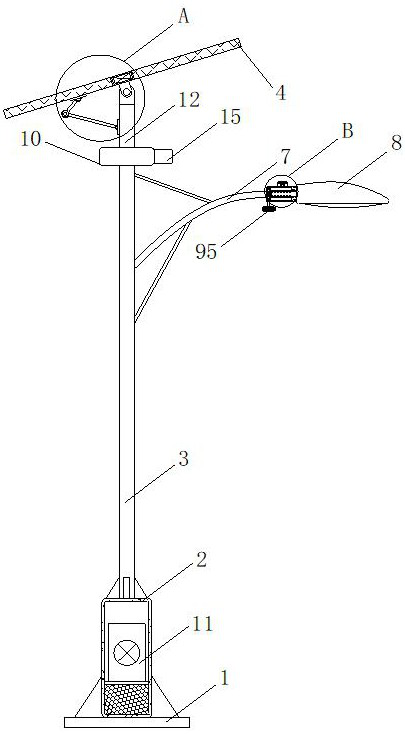
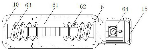
[0031] see Figure 1-6 , the present invention provides a technical solution: an LED lighting device based on solar power generation, including a base 1, a connecting mechanism and an adjusting mechanism, a housing 2 is fixedly installed on the top of the base 1, and a housing 2 is fixedly installed on the top of the housing 2 A column 3, a box body 10 is fixedly installed on the top of the column 3, a connecting rod 12 is arranged on the top of the box body 10, a curved rod 7 is arranged on the connecting rod 12, an LED lamp 8 is arranged on one end of the curved rod 7, and the housing 2 A storage battery 11 is arranged inside, and the connection mechanism is composed of a side plate 16, a support plate 17, a cross bar 18 and an installation assembly 9. 7 is fixedly connected, the installation component 9 is set on the side plate 16, a positioning groove is opened on the support plate 17, the cross bar 18 is located in the positioning groove, the adjustment mechanism is compo...

Embodiment 2

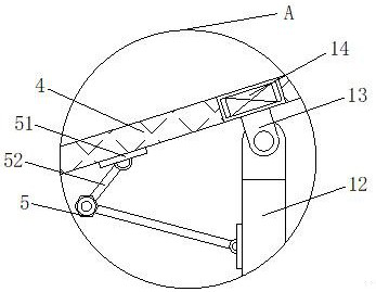
[0035] see Figure 1-6 , on the basis of Embodiment 1, the angle adjustment assembly 5 includes a sheet plate 51, a hinged rod 52, a connecting rod 53, a circular sleeve 54, a stopper 55 and a clamping nut 56, and the number of sheet plates 51 is two groups and respectively The bottom of the solar panel 4 and one side of the connecting rod 12 are all fixedly installed. The number of the hinged rods 52 is two groups and they are respectively hingedly installed on the outer walls of the two groups of plates 51. The connecting rods 53 are arranged on one end of the two groups of hinged rods 52. , the number of circular sleeves 54 is two groups and is movably sleeved on the outer wall of the connecting rod 53, one end of the hinged rod 52 is fixedly connected with the circular sleeve 54, the outer wall of the connecting rod 53 is fixedly equipped with a stopper 55, and one set of connecting rods 53 is located The outer wall of the circular sleeve 54 is in contact, the outer wall o...


PUM


Abstract

The invention discloses LED lighting equipment based on solar power generation and relates to the technical field of LED lighting. The LED lighting equipment based on solar power generation comprises a base, a connecting mechanism and an adjusting mechanism, wherein a shell is fixedly installed at the top of the base, a stand column is fixedly installed at the top of the shell, a box body is fixedly installed at the top of the stand column, and a connecting rod is arranged at the top of the box body. According to the LED lighting equipment based on solar power generation, the orientation of the solar panel can be automatically adjusted according to illumination intensity when the equipment is used in the daytime, and compared with the situation that orientation of the solar panel is always located at one position angle and cannot be adjusted, the light energy absorption effect of the solar panel is enhanced; the situation that the LED lamp cannot illuminate due to insufficient electric quantity of the storage battery is reduced, the equipment tends to be more intelligent, the LED lamp can illuminate automatically in dark weather, illumination control is not needed, and the intelligent effect of the illumination equipment is further improved.

Description

technical field [0001] The invention relates to the technical field of LED lighting, in particular to an LED lighting device based on solar power generation. Background technique [0002] In daily life, it is easier to see that LED lighting equipment that uses solar power generation is generally a street lamp, but some existing street lamps based on solar power generation cannot effectively adjust the orientation of the solar panel, causing the sun to rise and set. In the solar panel, the solar panel is always in a specific position and cannot be adjusted automatically following the sun’s trajectory, which wastes a lot of light energy and causes the converted electric energy to be insufficient for the long-term use of the LED lighting, which indirectly causes the solar power generation of the LED The lighting equipment is not intelligent enough, and there is room for improvement. Contents of the invention [0003] The purpose of the present invention is to solve at least ...

Claims


Application Information

Patent Timeline
Patent Type & Authority Applications(China)
IPC IPC(8): F21S9/03H02S20/32F21V21/116F21V23/04B01D53/26F21Y115/10F21W131/103
CPCF21S9/035H02S20/32F21V21/116F21V23/0464B01D53/26F21W2131/103F21Y2115/10Y02E10/50Y02B20/72
Inventor 姚源满
Owner 深圳亿同电子科技有限公司
Learn More