
A groove-type inclined shaft, tunnel structure and design method for preventing sand inrush during operation period

A design method and groove-type technology, applied in tunnels, design optimization/simulation, computer-aided design, etc., can solve problems such as endangering the safety of tunnel operations

Active Publication Date: 2022-04-08
CHINA RAILWAY ERYUAN ENG GRP CO LTD
View PDF4 Cites 0 Cited by
  • Summary
  • Abstract
  • Description
  • Claims
  • Application Information

AI Technical Summary

Problems solved by technology

[0005] The purpose of the present invention is to: the high-speed water flow in the prior art carries sand and gravel through the concrete blockage and enters the main tunnel, which seriously endangers the operation safety of the main tunnel; Pressure, the collapse of the plugging structure will still pose a huge risk to the main tunnel, and a groove-type inclined shaft, tunnel structure and design method for preventing sand inrush during the operation period are provided

Method used


Image

  • A groove-type inclined shaft, tunnel structure and design method for preventing sand inrush during operation period
  • A groove-type inclined shaft, tunnel structure and design method for preventing sand inrush during operation period
  • A groove-type inclined shaft, tunnel structure and design method for preventing sand inrush during operation period

Examples


Embodiment 1

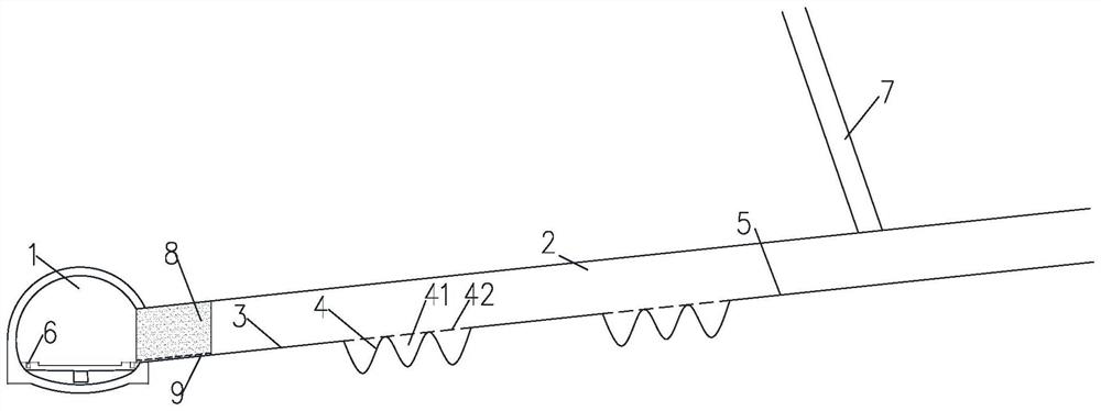
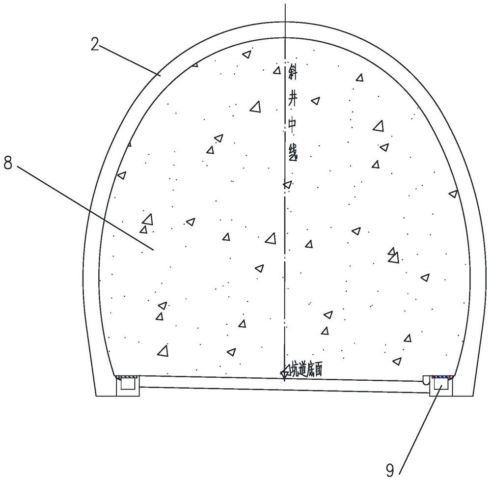
[0045] Such as figure 1 , 2 , 4 and 5, a groove-type inclined well for preventing sand inrush during the operation period described in this embodiment, the inclined well passes through the water-rich fault 7, including the inclined well channel 2, and the downstream of the inclined well channel 2 A plugging structure 8 is provided at the end, and a groove 41 for accommodating sand blasting is provided at the lower part of the well wall of the inclined shaft channel 2 .

[0046] On the basis of the above, in a further preferred manner, the groove 41 is in a wave shape along the longitudinal direction of the inclined shaft channel 2, so that the groove is not easy to collapse.

[0047] On the basis of the above, in a further preferred manner, the top of the groove 41 is covered with a steel wire mesh 42 to prevent larger stones from entering the groove 41 .

[0048] On the basis of the above, in a further preferred manner, an early warning device is provided in the inclined sh...

Embodiment 2

[0056] Such as figure 1 , 2 , 4 and 5, a kind of tunnel structure described in the present embodiment includes the groove type inclined shaft for preventing sand inrush during the operation period described in the positive tunnel 1 and embodiment 1, and the plugging structure 8 is arranged in The inclined shaft channel 2 is close to the end of the main hole 1 , and the bottom of the sealing structure 8 is provided with a drainage channel 9 , and the drainage channel 9 communicates the inclined shaft channel 2 and the main hole 1 .

[0057] On the basis of the above, in a further preferred manner, a drainage ditch is arranged in the main hole 1, and the drainage channel 9 communicates with the drainage ditch.

[0058] Specifically, the drainage ditch is the side ditch 6 of the main hole or the central gutter.

[0059] The beneficial effects of this embodiment: use the groove 41 to collect sand, reduce the total kinetic energy of sand in the inclined shaft channel 2, prevent t...

Embodiment 3

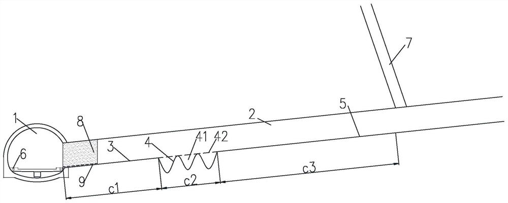
[0061] Such as Figure 1-Figure 5 As shown, a design method described in this embodiment is used to calculate the width s of the groove 41 and the length C of the groove segment 4 2 , specifically: Contains the following steps:

[0062] S1: Establish a deviated well design model based on the grooved inclined well for sand inrush prevention during the operation period described in Embodiment 1 or 2, and make the deviated well design model satisfy: input drainage section 3 flow rate b 1 and flow rate b of sand gushing section 5 3 Get the length C of groove segment 4 2 and the operational relationship between the width s of the groove 41;

[0063] S2: The width s of the groove 41 is proposed according to the maximum lateral dimension A of the bottom of the cross section of the inclined shaft channel 2, s≤A, based on the width s of the groove 41 and the length C of the groove segment 4 2 and the operational relationship between the width s of the groove 41, the length C of the...


PUM


Abstract

The invention relates to the field of tunnel engineering, in particular to a groove-type inclined shaft, a tunnel structure and a design method for preventing sand inrush during the operation period, wherein the inclined shaft includes a channel for the inclined shaft, and a plugging structure is arranged at the downstream end of the channel , the inclined shaft channel includes a sand gushing section, a groove section and a drainage section arranged in sequence along its length direction. The drainage section is located at the downstream end of the inclined shaft channel, and the sealing structure is located in the drainage section. The groove for containing the sand surge is covered with a steel wire mesh on the top of the groove. A kind of groove-type inclined well for preventing sand inrush during the operation period of the present invention, a groove is arranged in the groove section upstream of the drainage section, and the groove is used to collect sand gushing, so as to reduce the total kinetic energy of sand gushing in the channel of the inclined shaft, and deposit sand Finally, it prevents the blocking structure from clogging, and avoids the damage caused by the huge static pressure to the sealing structure and even the main hole. At the same time, the top of the groove is covered with a steel wire mesh to prevent large stones from entering the groove and causing the groove to collect sand. The effect becomes worse.

Description

technical field [0001] The invention relates to the field of tunnel engineering, in particular to a groove-type inclined shaft for preventing sand inrush during operation, a tunnel structure and a design method. Background technique [0002] During the construction of long tunnels, in order to meet the requirements of construction period and construction safety, auxiliary tunnels such as inclined shafts need to be built. However, when the inclined well passes through water-rich faults, karst and other sections, sand gushes are prone to occur, which seriously endangers the operation safety of the main tunnel. [0003] In the prior art, concrete plugging is generally arranged at the intersection of the inclined shaft and the main tunnel, and drainage channels are reserved. However, if a sand gushing accident occurs in the inclined shaft, the sealing structure cannot withstand the huge impact force, and the high-speed water will carry sand and gravel to break through the concr...

Claims


Application Information

Patent Timeline
Patent Type & Authority Patents(China)
IPC IPC(8): E21D9/14E21F16/00E21F16/02G06F30/13G06F30/28G06F113/08G06F119/14
CPCE21D9/14E21F16/00E21F16/02G06F30/13G06F30/28G06F2113/08G06F2119/14
Inventor 范雲鹤郑长青赵万强喻渝周羽哲张永平琚国全汤印华阳杨学中王闯陈拴
Owner CHINA RAILWAY ERYUAN ENG GRP CO LTD
Learn More