A USB power cable auxiliary packaging device
A power connection line and packaging equipment technology, applied in connection, dust-proof/splash-proof/leak-proof/waterproof/fireproof connection, packaging, etc., can solve the problems of many operation steps and low safety, and achieve high work efficiency , easy to remove the effect of processing
- Summary
- Abstract
- Description
- Claims
- Application Information
AI Technical Summary
Problems solved by technology
Method used
Image

Examples
Embodiment 1
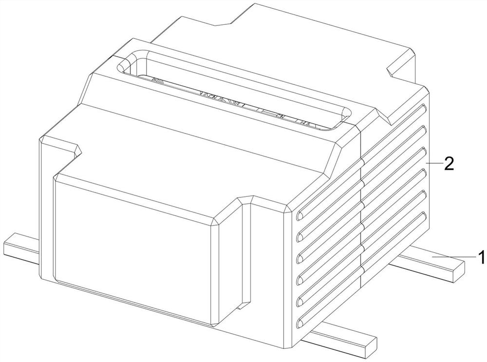
[0074] A USB power cable auxiliary packaging device, such as Figure 1-Figure 7 As shown, it includes a support rod 1, an outer cover 2, a heating rod 3, a guide mechanism 4, an adsorption mechanism 5 and a welding mechanism 6, the front and rear sides of the bottom of the outer cover 2 are connected with a support rod 1, and the inner lower part of the outer cover 2 is provided with a guiding mechanism 4 The guide mechanism 4 is provided with an adsorption mechanism 5, the inner upper part of the outer cover 2 is provided with a welding mechanism 6, and the welding mechanism 6 is provided with two heating rods 3.
[0075] The guide mechanism 4 includes a first mounting frame 41 , a first sliding frame 42 , a first spring 43 and a sliding connecting plate 44 , and a first mounting frame 41 is provided in the middle of the lower part of the left and right sides of the inner wall of the outer cover 2 . A first sliding frame 42 is provided in a sliding type, and a sliding connect...
Embodiment 2
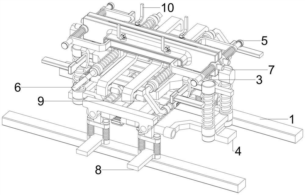
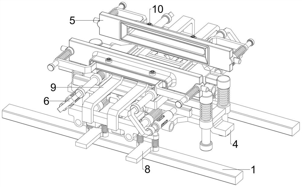
[0080] On the basis of Example 1, as figure 2 , image 3 , Figure 8 , Figure 9 , Figure 10 , Figure 11 and Figure 12 As shown, an exhaust mechanism 7 is also included. The exhaust mechanism 7 includes a limit block 71, a limit rod 72 and a limit frame 73. There are limit blocks 71 in the middle of the upper left and right sides of the inner wall of the outer cover 2. The limit blocks 71 Located above the clamp rod 65, the sealing cover 52 is provided with limit rods 72 on the left and right sides. The limit rods 72 cooperate with the limit blocks 71. The upper left and right sides of the inner wall of the outer cover 2 are symmetrically provided with limit frames 73 front and rear. The limit frames 73 Cooperate with piston 54 .
[0081] When the first sliding frame 42 and the sliding connecting plate 44 move downward, the sliding connecting plate 44 drives all the components on it to move downward. When the piston 54 is in contact with the limit frame 73, the limit...
Embodiment 3
[0086] On the basis of Example 2, as figure 2 , image 3 , Figure 13 , Figure 14 and Figure 15 As shown, it also includes a disengagement mechanism 10. The disengagement mechanism 10 includes a pressure rod 1001, a ventilation valve 1002, a second guide rod 1004, a baffle 1005 and a sixth spring 1006. The pressure rod 1001 and the upper part of the sealing cover 52 are symmetrically provided with a vent valve 1002, a plurality of air vent holes 1003 are opened on the vent valve 1002, and a second guide rod 1004 is slidably provided in the middle of the vent valve 1002. The second guide rod 1004 In cooperation with the pressure rod 1001, the bottom of the second guide rod 1004 is provided with a baffle 1005, the baffle 1005 is located inside the ventilation valve 1002, the upper part of the second guide rod 1004 is provided with a sixth spring 1006, and the two ends of the sixth spring 1006 are respectively connected to the upper part of the second guide rod 1004. The s...
PUM
 Abstract
Description
Claims
Application Information
 - R&D
- Intellectual Property
- Life Sciences
- Materials
- Tech Scout
- Unparalleled Data Quality
- Higher Quality Content
- 60% Fewer Hallucinations
Browse by: Latest US Patents, China's latest patents, Technical Efficacy Thesaurus, Application Domain, Technology Topic, Popular Technical Reports.
© 2025 PatSnap. All rights reserved.Legal|Privacy policy|Modern Slavery Act Transparency Statement|Sitemap|About US| Contact US: help@patsnap.com