
Wind power generation speed reducer

A technology of reducer and locking mechanism, applied in mechanical equipment, transmission parts, belts/chains/gears, etc., can solve the problems of oil contamination of the service life, large deceleration, and easy vibration of the reducer for wind power generation. The effect of reducing frequent replacement of filter elements, improving clamping effect and improving service life

Pending Publication Date: 2021-10-26
程林
View PDF0 Cites 0 Cited by
  • Summary
  • Abstract
  • Description
  • Claims
  • Application Information

AI Technical Summary

Problems solved by technology

[0004] The purpose of the present invention is to solve the problem that on the one hand, the reducer for wind power generation has a large deceleration ratio and is easy to vibrate, so a stable installation form is required; on the other hand, oil pollution will accelerate the wear of the gears inside the reducer for wind power generation and reduce To solve the problem of the service life of the reducer, a wind power generation reducer is proposed

Method used


Image

  • Wind power generation speed reducer
  • Wind power generation speed reducer
  • Wind power generation speed reducer

Examples


Embodiment

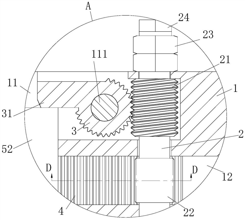
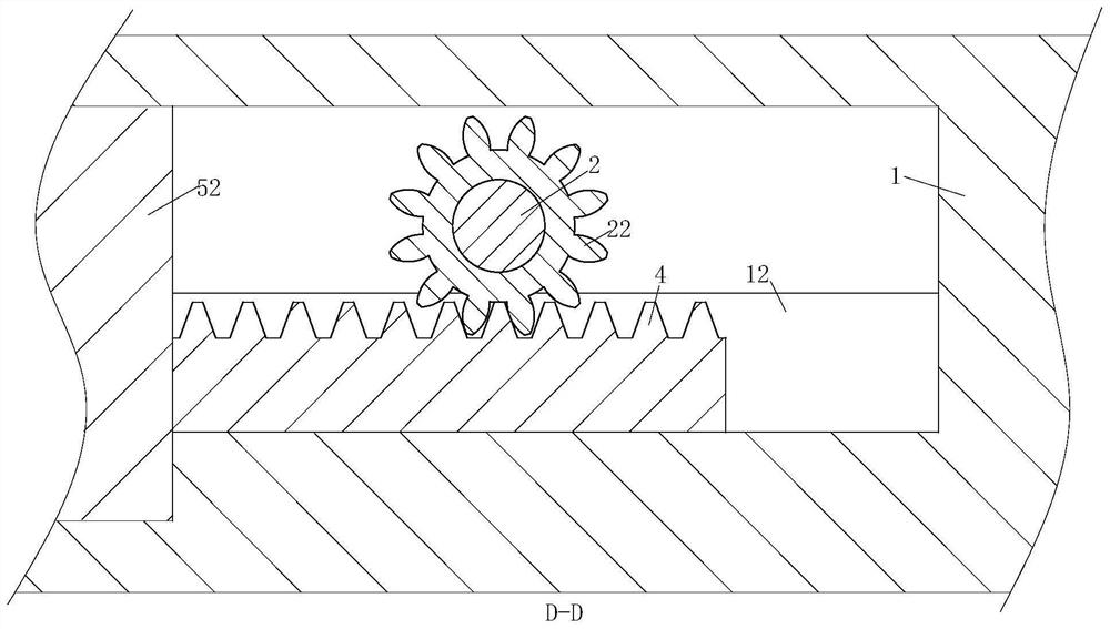
[0029] refer to Figure 1-5 , a reducer for wind power generation, comprising a mounting platform 1, a reducer body 5 and a base 52 fixedly connected to the reducer body 5, the mounting platform 1 is provided with a placement slot 11, and the base 52 is locked by a lock The tightening mechanism is fixed in the placement groove 11. The locking mechanism includes a torsion bar 2, which is rotatably connected with the mounting table 1. The torsion bar 2 is provided with a worm 21 and a gear 22 sequentially from top to bottom. A worm wheel 3 meshed with the worm 21 is rotatably connected in the placement groove 11, and a locking block 31 is fixedly connected to the worm wheel 3, and the locking block 31 fits with the top wall of the base 52, and the placement groove 11 A chute 12 is arranged inside, and a rack 4 is slidably connected to the chute 12, and the rack 4 is meshed with the gear 22;

[0030] One end of the reducer body 5 is rotatably connected with a drive shaft 51, and...

Embodiment approach

[0032] As a specific embodiment of the present invention, a positioning shaft 111 is fixedly connected in the placement slot 11 , and the worm wheel 3 is rotatably connected to the positioning shaft 111 .

[0033] As a specific embodiment of the present invention, the top of the torsion bar 2 is provided with a rectangular locking head 24. In the present invention, the rectangular locking head 24 on the top of the torsion bar 2 can facilitate the clamping and exerting force of the wrench, and facilitate the installation. sex.

[0034] As a specific embodiment of the present invention, lock nuts 23 are threadedly connected to the torsion bar 2, and the number of the lock nuts 23 is specifically two groups. The present invention uses double nuts 23 for locking to prevent the torsion bar from 2 Reversed to improve the locking reliability of the locking mechanism to the base 52.

[0035] As a specific embodiment of the present invention, the filter module 6 includes a filter cyli...


PUM


Abstract

The invention relates to the technical field of wind power generation, in particular to a wind power generation speed reducer which comprises a mounting table, a speed reducer body and a base fixedly connected to the speed reducer body, a placing groove is formed in the mounting table, and the base is fixed in the placing groove through a locking mechanism; the locking mechanism comprises a torsion bar, the torsion bar is rotationally connected with the mounting table, a worm and a gear are fixed to the torsion bar, a worm gear meshed with the worm is rotationally connected into the placing groove, a locking block is fixedly connected to the worm gear, a sliding groove is formed in the placing groove, a rack is slidably connected into the sliding groove, and the rack is meshed with the gear; and an oil outlet in the upper end of the speed reducer body is communicated with a filtering module. The locking block and the rack are used for right-angle clamping of the top wall and the side wall of the base, the effect is reliable, operation is convenient, and the efficiency is high; and the filtering module is used for filtering oil liquid, abrasion of parts in the speed reducer is reduced, and the service life of the speed reducer is prolonged.

Description

technical field [0001] The invention relates to the technical field of wind power generation, in particular to a speed reducer for wind power generation. Background technique [0002] The reducer plays the role of matching speed and transmitting torque between the prime mover and the working machine or the actuator. The reducer is a relatively precise machine. The purpose of using it is to reduce the speed and increase the torque. According to the number of transmission stages, it can be It is divided into single-stage and multi-stage reducers; according to the shape of the gear wheel, it can be divided into cylindrical gear reducers, bevel gear reducers and conical-cylindrical gear pulley reducers, which are often used as reduction transmission between the driving part and the working machine The device plays the role of matching speed and transmitting torque between the prime mover and the working machine or the actuator, which is very common on wind turbines. [0003] In...

Claims


Application Information

Patent Timeline
Patent Type & Authority Applications(China)
IPC IPC(8): F16H57/025F16H57/028F16H57/04
CPCF16H57/025F16H57/028F16H57/0402F16H57/0404F16H57/0408F16H57/0434F16H2057/02078
Inventor 程林季越
Owner 程林
Learn More