Light emitting diode driving system

A technology of light-emitting diodes and driving systems, applied in electrical components and other directions, can solve the problems of high failure rate, unsatisfactory stability and reliability, low flexibility of use, etc., to improve the voltage value, improve the control flexibility, The effect of improving stability and reliability

Pending Publication Date: 2021-10-22
宁波市芯能微电子科技有限公司
View PDF0 Cites 0 Cited by
  • Summary
  • Abstract
  • Description
  • Claims
  • Application Information

AI Technical Summary

Problems solved by technology

However, the existing RGB-LED strip driving system usually uses a single driver chip to drive all the RBG lamp beads, which not only has low flexibility, but also has a high failure rate, and the stability and reliability are not ideal.

Method used


Image

  • Light emitting diode driving system
  • Light emitting diode driving system
  • Light emitting diode driving system

Examples


Embodiment 1

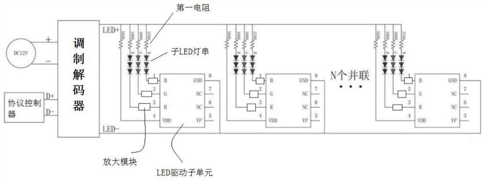
[0017] Embodiment 1: a kind of LED driving system, such as figure 1 As shown, it includes a modulation decoder, the input end of the modulation decoder is connected with a first power supply and a protocol controller; the output end of the modulation decoder is connected in parallel with a plurality of LED driving subunits, and the LED driving subunit includes a driving subchip, and the driving subunit The input terminal of the chip is connected with multiple color sub-wires, on which there are sub-LED light strings and first resistors, and the other end of the color sub-wires is connected to the positive lead-out wire of the modulation decoder; the ground terminal of the LED driving sub-unit is connected to the The negative lead wire of the modulation decoder is connected. The invention controls the LED light strings on each color sub-line through multiple driving sub-chips, which greatly improves the control flexibility of the LED light strings, and the multiple LED light st...


PUM


Abstract

The invention discloses a light emitting diode driving system which comprises a modulation decoder, and the input end of the modulation decoder is connected with a first power supply and a protocol controller. The output end of the modulation decoder is connected in parallel with a plurality of LED driving sub-units, each LED driving sub-unit comprises a driving sub-chip, the input end of each driving sub-chip is connected with a plurality of color sub-lines, each color sub-line is provided with a sub-LED lamp string and a first resistor, and the other end of each color sub-line is connected with an anode outgoing line of the modulation decoder; and the grounding end of the LED driving sub-unit is connected with the negative electrode outgoing line of the modulation decoder.

Description

technical field [0001] The invention relates to a light-emitting diode driving system for an LED light strip, and belongs to the technical field of light-emitting diodes. Background technique [0002] The existing RGB-LED light strip refers to the assembly of LED lamp beads and chip resistors on a strip-shaped FPC (flexible circuit board) or PCB hard board. The RGB circuit board is covered with high-quality PI layers on both sides, and half a meter is connected to one meter. Or one meter is a body, weld four parallel wires at the front end and connect them to the four core wires covered with rubber, and then perform secondary rubber wrapping and other processes, and add an external RGB dedicated controller power supply to output a positive pole of the power supply and three wires. RGB negative line, RGB light color conversion lighting, RGB-LED light strips are suitable for LED lighting design solutions such as building decoration and stage lighting systems. However, the exi...

Claims


Application Information

Patent Timeline
IPC IPC(8): H05B45/20H05B45/30H05B45/50
CPCH05B45/20H05B45/30H05B45/50
Inventor 林丰成王保峰杨海申冉承新董侃张力周炯李晓中
Owner 宁波市芯能微电子科技有限公司
Why Eureka
Try Eureka