Material damage positioning device, positioning method and verification method
A technology for positioning devices and material damage, which is applied in the direction of measuring devices, analyzing materials, and using acoustic wave emission technology for material analysis, etc., can solve the problems of reduced bearing capacity and complexity, and achieve low cost, simple equipment, and a small number of sensors.
- Summary
- Abstract
- Description
- Claims
- Application Information
AI Technical Summary
Problems solved by technology
Method used
Image
Examples
Embodiment 1
[0045] First analyze the method of detecting the azimuth angle of the damage position:
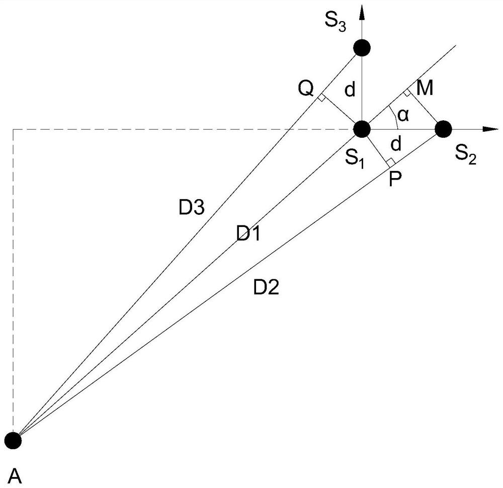
[0046] refer to figure 1 As shown, at least three acoustic emission sensors (S 1 , S 2 and S 3 ) method for detecting the azimuth angle of the damaged position:
[0047] Connect the three receiving sensors S 1 , S 2 and S 3 Mounted on composite material plate, position S1 , S 2 and S 3 The exemplary distance between the three sensors at is set to be d. The following is an example where three sensors are arranged in a right triangle arrangement, if the three sensors S 1 , S 2 , S 3 The coordinates are expressed as (x 1 ,y 1 ), (x 2 ,y 2 ) and (x 3 ,y 3 ). Then it is clear from the right triangle that x 2 =x 1 +d,x 3 =x 1 ,y 2 =y 1 and y 3 =y 1 +d. Let the coordinates of sound source A be (x A ,y A ).
[0048] Suppose three lines AS 1 , AS 2 and AS 3 are parallel, which should be the case when the AE source is far from the sensor, AS 2 -AS 1 =c(α)t 21 , AS...
Embodiment 2
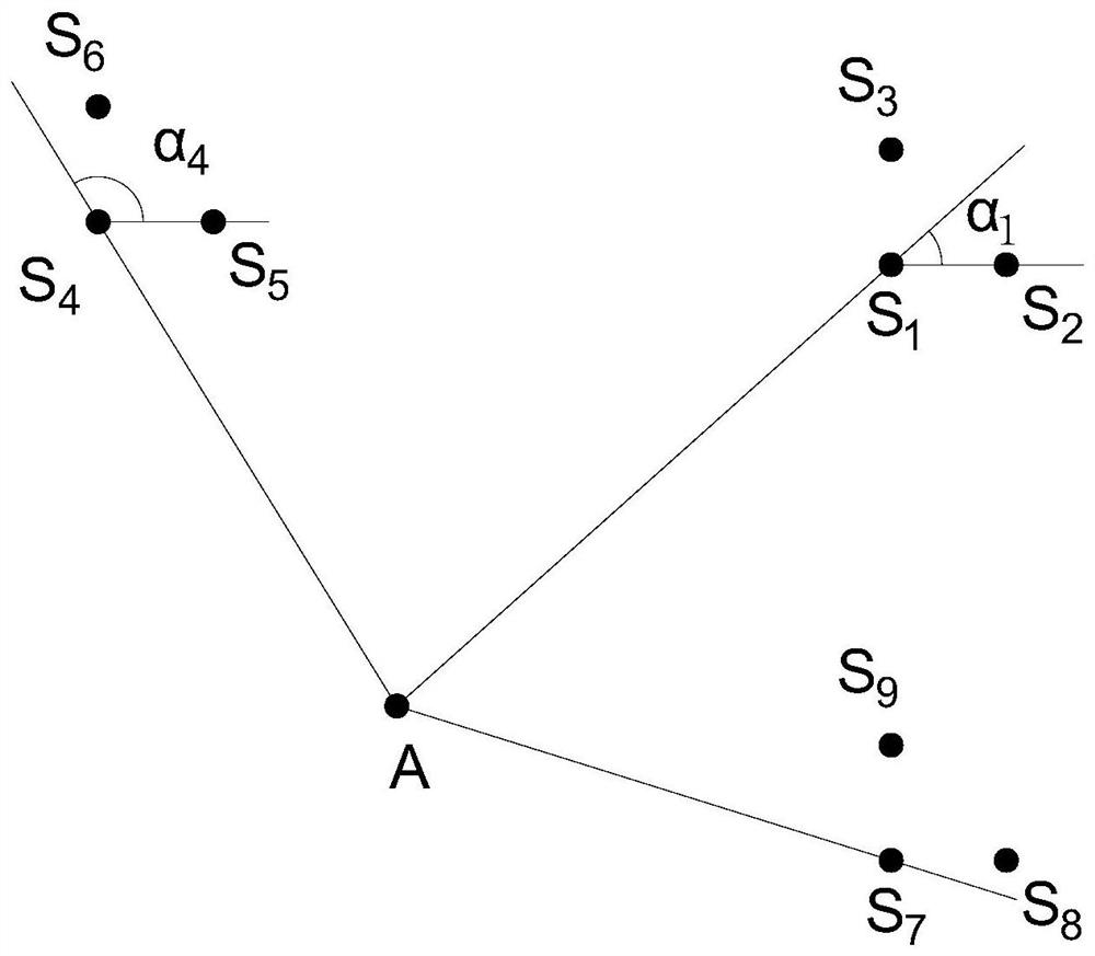
[0061] refer to figure 2 , Figure 7 As shown, the present disclosure provides a material damage localization device, comprising:
[0062] At least two sensor groups, each sensor group illustratively includes three acoustic emission sensors, in this embodiment, three acoustic emission sensors in the same group are exemplary arranged on the three vertices of a right triangle, and the sensor groups use It is installed on the material to be tested and receives the sound wave signal reflected by the damage position at different positions. The two sensor groups are the first sensor group and the second sensor group, which can be at the first preset distance from the area to be tested. A first sensor group is provided at , wherein the first sensor group includes at least the sensor S 1 , sensor S 2 , sensor S 3 , the first sensor group can measure the direction angle α of the damage position relative to the position of the first sensor group 1 ; A second sensor group is provid...
Embodiment 3
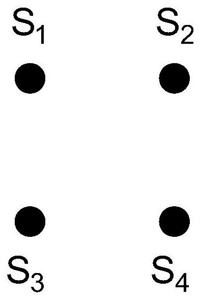
[0066] refer to image 3 As shown, in one implementation, the sensor group includes four acoustic emission sensors, and the four acoustic emission sensors in the same group (S 1 , S 2 , S 3 , S 4 ) are arranged on the four vertices of the square, where the sensor S 1 , sensor S 2 , sensor S 4 Can form a group of sensors, sensor S 2 , sensor S 4 , sensor S 3 Can form a group of sensors, sensor S 4 , sensor S 3 , sensor S 1 Can form a group of sensors, sensor S 3 , sensor S 1 , sensor S 2 A group of sensor groups can be formed, and one sensor group can form four small sensor groups at the same position. Through the signal time information detected by any three acoustic emission sensors mentioned above, a direction angle α can be calculated, and multiple directions detected The angle α can be mutually verified, and at the same time, the 4 direction angles obtained by the 4 isosceles right triangle sensor groups can be normalized to reduce errors. Two sets of square...
PUM
 Abstract
Description
Claims
Application Information
 - R&D
- Intellectual Property
- Life Sciences
- Materials
- Tech Scout
- Unparalleled Data Quality
- Higher Quality Content
- 60% Fewer Hallucinations
Browse by: Latest US Patents, China's latest patents, Technical Efficacy Thesaurus, Application Domain, Technology Topic, Popular Technical Reports.
© 2025 PatSnap. All rights reserved.Legal|Privacy policy|Modern Slavery Act Transparency Statement|Sitemap|About US| Contact US: help@patsnap.com


