
Hydraulic pulsation fatigue test device for axle

A fatigue test and hydraulic technology, applied in the direction of measuring device, vehicle test, vehicle suspension/shock absorbing mechanism test, etc., to achieve the effect of improving the scope of application

Pending Publication Date: 2021-10-22
ANHUI ANKAI FUTIAN SHUGUANG AXLE CO LTD
View PDF1 Cites 0 Cited by
  • Summary
  • Abstract
  • Description
  • Claims
  • Application Information

AI Technical Summary

Problems solved by technology

[0005] The purpose of the present invention is to provide a hydraulic pulsation fatigue test device for vehicle axles, which can solve the existing problems

Method used


Image

  • Hydraulic pulsation fatigue test device for axle
  • Hydraulic pulsation fatigue test device for axle
  • Hydraulic pulsation fatigue test device for axle

Examples


Embodiment 1

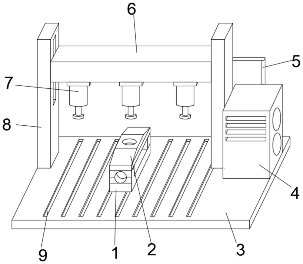
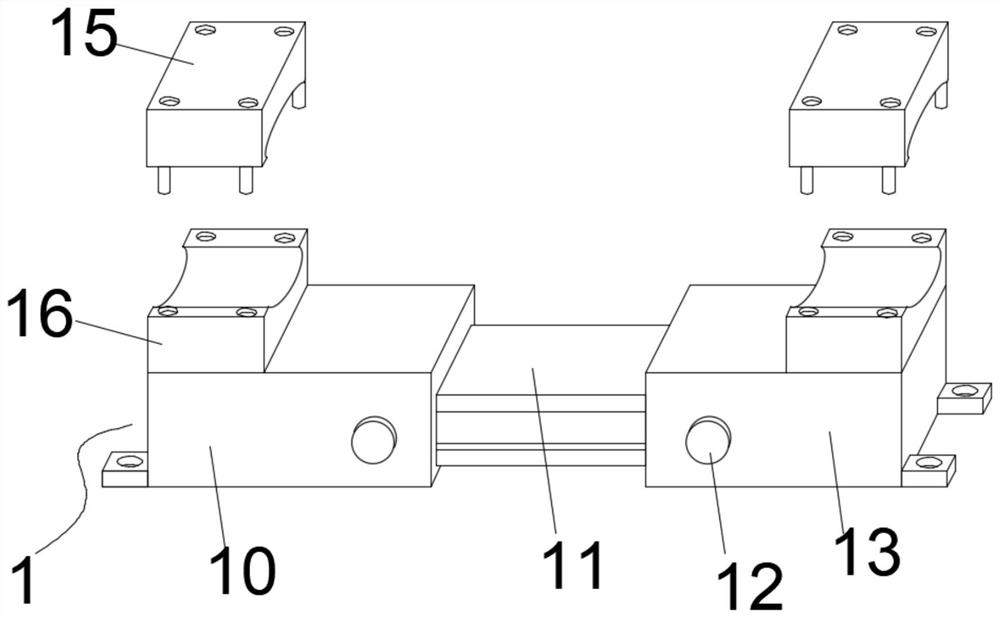
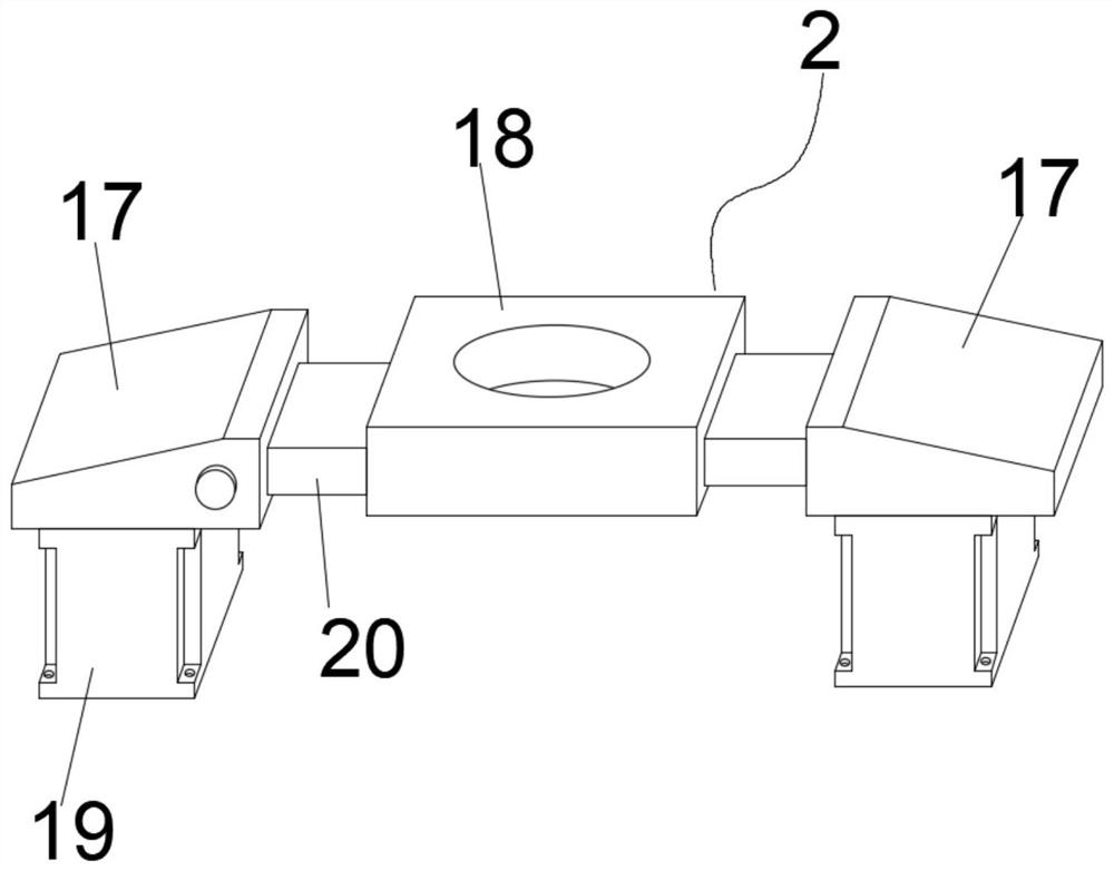
[0029] The gantry fixed frame 2 comprises a fixed foot frame 17 and a docking sleeve plate 18, and a circular notch runs through the inner middle part of the butt joint sleeve plate 18. The number of the fixed foot frame 17 is two groups, and the fixed foot frame 17 is movably installed on the butt joint. At the two ends of the cover plate 18, the second expansion plate 20 is sleeved between the fixed foot frame 17 and the butt joint cover plate 18, and the bottom of the fixed foot frame 17 is fixedly equipped with a support block 19. By using the setting of the second expansion plate 20, the When the fatigue test device is used for testing different types of vehicle axles, the fixed foot frame 17 can be pulled, and the second telescopic plate 20 can be extracted from between the fixed foot frame 17 and the docking sleeve plate 18, thereby adjusting the use of the gantry fixed frame 2 length, so that the gantry fixing frame 2 can be adjusted accordingly according to the length ...

Embodiment 2

[0032]The two sides of the pulse head 7 are provided with a gantry 8, and the pulse head 7 and the gantry 8 are movably connected by the lifting frame 6. The outer surface of the side of the gantry 8 is provided with a lifting chute, and the gantry 8 is driven by a hydraulic method. frame 6, so that the lifting frame 6 can drive the pulse head 7 to move up and down, so that the pulse head 7 can be inserted into the circular slot of the docking sleeve plate 18 after moving, so that it is convenient to carry out hydraulic pulsation fatigue test on the installed axle structure .

[0033] A hydraulic cylinder 4 is installed on one side of the gantry 8, and an oil pipe 5 is arranged between the hydraulic cylinder 4 and the pulse head 7. The hydraulic cylinder 4 is used to provide power for the pulse head 7 through the oil pipe 5, so that the pulse head 7 moves downward, and the vehicle Bridge structure for test operation.

[0034] The upper part of the shaft clamp 16 is fixedly sl...


PUM


Abstract

The invention discloses a hydraulic pulse fatigue test device for an axle comprises a supporting seat and a pulse head, the pulse head is movably installed on the upper portion of the supporting seat, the upper portion of the supporting seat is fixedly sleeved with a gantry fixing frame, the supporting seat comprises a first clamping seat and a second clamping seat, the second clamping seat is movably installed on one side of the first clamping seat, a first telescopic plate is movably connected between the first clamping seat and the second clamping seat in a sleeved mode. Two shaft head clamps are fixedly installed on the upper portion of the supporting seat. A lifting frame is used for driving the pulse head to move downwards, the pulse head is inserted into a circular notch of a gantry fixing frame, one end of the pulse head abuts against an axle, a hydraulic cylinder is matched with an oil pipe to drive the pulse head, and the pulse head conducts testing operation on the axle; by means of the arrangement of the supporting seat and the first telescopic plate, the hydraulic pulsation fatigue test device for the axle is provided with a fixed adjusting structure, so that the hydraulic pulsation fatigue test device is suitable for axles of different models, and the application range is widened.

Description

technical field [0001] The invention belongs to the technical field of vehicle axle testing, in particular to a hydraulic pulsation fatigue test device for vehicle axles. Background technique [0002] The automobile axle (also known as the axle) is connected to the vehicle frame (or load-bearing body) through the suspension, and the wheels are installed at both ends. The function of the axle is to bear the load of the automobile and maintain the normal driving of the automobile on the road. [0003] Patent No. CN211668766U discloses a utility model document for a vehicle axle testing device, which includes a base. The top of the base is slidingly connected with two mobile brackets. The end of the mobile bracket away from the base is connected with a fixed plate. The top of the fixed plate is connected with a working tube. The inner wall of the tube is slidingly connected to the piston, the outer wall of the piston is connected with a first elastic element, the first elastic ...

Claims


Application Information

Patent Timeline
Patent Type & Authority Applications(China)
IPC IPC(8): G01M17/007G01M17/04
CPCG01M17/007G01M17/04
Inventor 牛家忠邾枝润李兆杰张海波丁飞
Owner ANHUI ANKAI FUTIAN SHUGUANG AXLE CO LTD
Learn More