An automatic device for penetrating long steel bars into multi-section heat-shrinkable tubes

An automation device and technology of heat-shrinkable tubes, which are applied in the field of railway equipment, can solve problems such as low productivity, installation deviations, and large position deviations, and achieve the effects of reducing labor intensity, accurate installation positions, and improving production efficiency

Active Publication Date: 2022-01-21
LIAONING METAL TECH
View PDF13 Cites 0 Cited by
  • Summary
  • Abstract
  • Description
  • Claims
  • Application Information

AI Technical Summary

Problems solved by technology

[0002] In actual production, heat-shrinkable sleeves are generally placed on the steel bars of the track slab skeleton manually. Because the track slab requires a large number of steel bars to pass through the tubes, and the installation position deviation is large during manual operation, the intensity of manual labor is large, and eventually it will The productivity is low. In addition, for steel bars of different lengths or uses, the actual installation position and quantity of the heat shrinkable sleeves are different, and the length of the selected heat shrinkable sleeves will also be different, so the manual installation operation will be more cumbersome. It is easy to cause deviations in installation, so it is necessary to accurately position the heat-shrinkable sleeve, facilitate the installation of long steel bars, and is suitable for the automation of long steel bar penetration into multi-section heat-shrinkable tubes for various types of heat-shrinkable sleeves and steel bar installation methods device

Method used


Image

  • An automatic device for penetrating long steel bars into multi-section heat-shrinkable tubes
  • An automatic device for penetrating long steel bars into multi-section heat-shrinkable tubes
  • An automatic device for penetrating long steel bars into multi-section heat-shrinkable tubes

Examples


Embodiment Construction

[0034] The following will clearly and completely describe the technical solutions in the embodiments of the present invention with reference to the accompanying drawings in the embodiments of the present invention. Obviously, the described embodiments are only some, not all, embodiments of the present invention. Based on the embodiments of the present invention, all other embodiments obtained by persons of ordinary skill in the art without making creative efforts belong to the protection scope of the present invention.

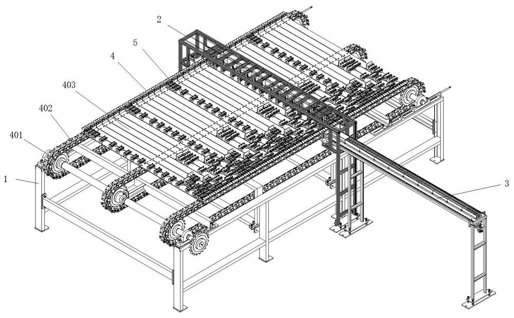
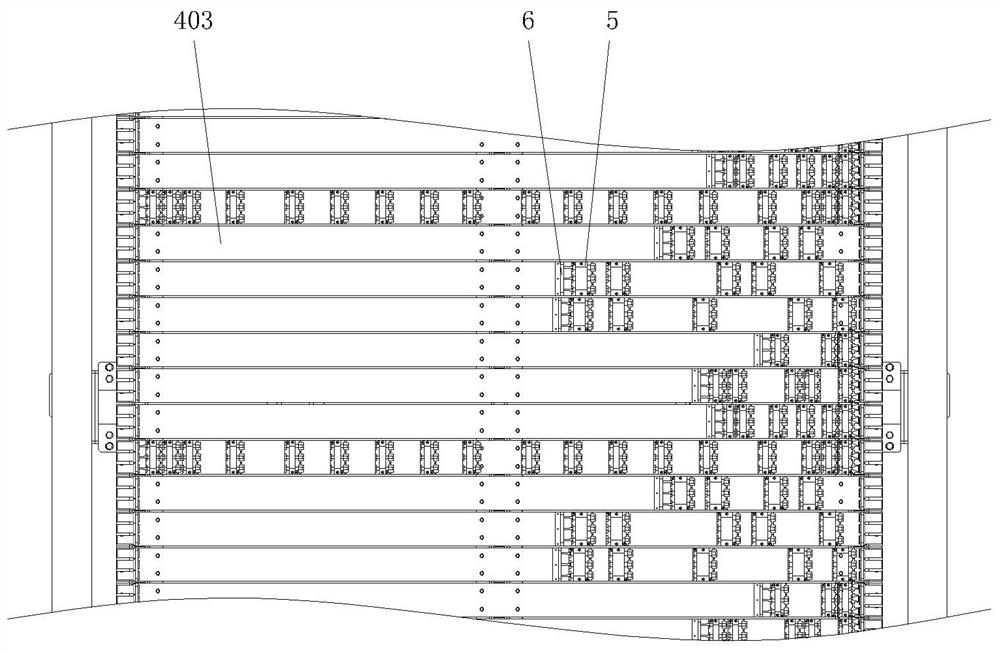
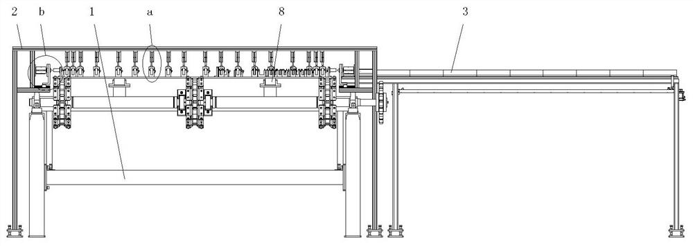
[0035] refer to Figure 1 to Figure 13 , an automatic device for penetrating long steel bars into multi-section heat-shrinkable tubes, including a main frame 1, a pressing device 2, a steel bar pushing device 3 and a chain conveying mechanism 4, and the chain conveying mechanism 4 is arranged on the main frame 1, and the chain conveying mechanism 4. Heating equipment can be installed at the rear position of the upper side, so that the heat-shrinkable sleeve ca...


PUM


Abstract

The invention discloses an automatic device for penetrating long steel bars into multi-section heat-shrinkable tubes, which belongs to the technical field of railway equipment and includes a main frame, a pressing device, a steel bar pushing device and a chain conveying mechanism. The surface of the chain conveying mechanism is fixedly equipped with heat-shrinkable tubes The positioning mechanism, the present invention can ensure the accuracy of the installation position of the heat-shrinkable sleeve through the chain conveying mechanism, the heat-shrinkable tube positioning mechanism, the pressing device and the steel bar pushing device, and can simultaneously carry out the movement and penetration of three groups of long steel bars, It reduces the labor intensity of workers and improves production efficiency. Through the structure in the pressing device, the position of the movable rod and the pressing mechanism can be adjusted, and then when installing steel bars and heat shrinkable sleeves of different specifications, it can Effective compression and positioning of heat shrinkable sleeves, through the structure of the compression mechanism, the length of the compression mechanism can be adjusted, suitable for heat shrinkable tube positioning mechanisms of different lengths, and can be used for heat shrinkable sleeves of different lengths Perform compression positioning.

Description

technical field [0001] The invention belongs to the technical field of railway equipment, and in particular provides an automatic device for penetrating long steel bars into multi-section heat-shrinkable tubes. Background technique [0002] In actual production, heat-shrinkable sleeves are generally placed on the steel bars of the track slab skeleton manually. Because the track slab requires a large number of steel bars to pass through the tubes, and the installation position deviation is large during manual operation, the intensity of manual labor is large, and eventually it will The productivity is low. In addition, for steel bars of different lengths or uses, the actual installation position and quantity of the heat shrinkable sleeves are different, and the length of the selected heat shrinkable sleeves will also be different, so the manual installation operation will be more cumbersome. It is easy to cause deviations in installation, so it is necessary to accurately posi...

Claims


Application Information

Patent Timeline
Patent Type & Authority Patents(China)
IPC IPC(8): B29C65/78B29C65/66
CPCB29C65/7858B29C65/7802B29C65/7841B29C65/66
Inventor 夏智明李召君刘洪波太生辉李全海李国宝刘航睿赵帅李丹丹孟丽莉王雅虹陈琳
Owner LIAONING METAL TECH
Why Eureka
Try Eureka