
Pile soil pressure monitoring system and monitoring method

A pressure monitoring and earth pressure technology, which is applied to the field foundation soil survey, construction, and foundation structure tests, etc., can solve the problems of poor burying effect, difficult and inconvenient burying, and complicated burying operation of test components, so as to improve the authenticity, On-site construction and earth pressure test are easy to operate, and the layout effect is good.

Active Publication Date: 2021-10-19
JIAN YAN FOUND ENG
View PDF4 Cites 0 Cited by
  • Summary
  • Abstract
  • Description
  • Claims
  • Application Information

AI Technical Summary

Problems solved by technology

[0003] The purpose of the present invention is to provide a pile soil pressure monitoring system, which solves the technical problems of complicated embedding operation, difficult and inconvenient embedding, and poor embedding effect of test elements in the prior art

Method used


Image

  • Pile soil pressure monitoring system and monitoring method
  • Pile soil pressure monitoring system and monitoring method
  • Pile soil pressure monitoring system and monitoring method

Examples


Embodiment Construction

[0030] In order to make the purpose, technical solutions and advantages of the embodiments of the present invention more clear, the technical solutions in the embodiments of the present invention will be clearly and completely described below in conjunction with the drawings in the embodiments of the present invention.

[0031] In the following description, the outer side refers to the side toward the pile side soil, and the inner side refers to the side toward the pile axis; the outer direction refers to the direction from the pile body axis to the pile side soil, and the inner direction refers to the direction from the pile body The side soil points to the direction of the axis of the pile body; the directions of "up", "down", "top" and "bottom" are only relative to the orientation of the reinforcement cage shown in the attached drawing, and vary with the actual direction of the reinforcement cage And change.

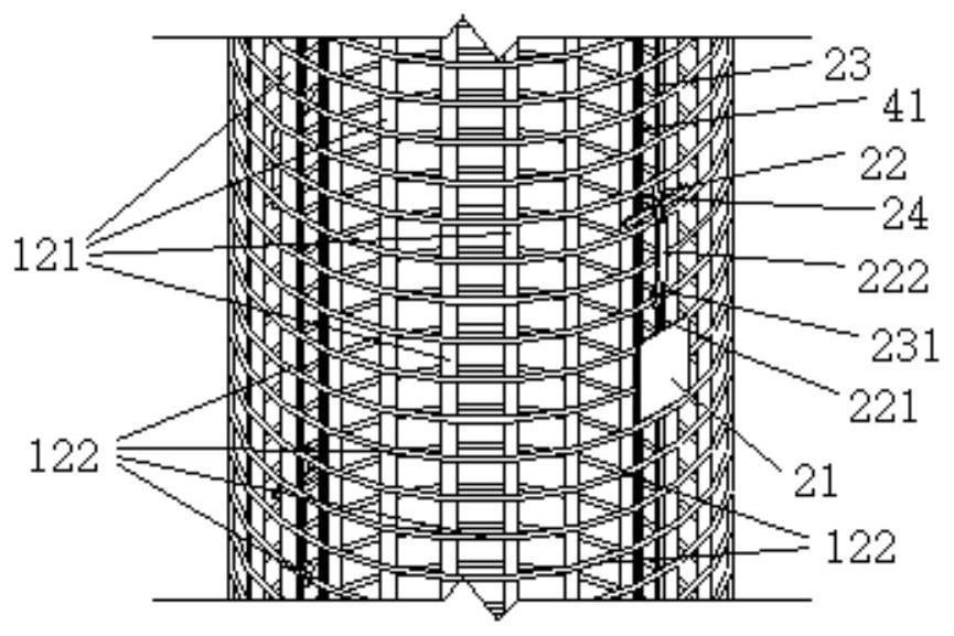
[0032] Such as Figure 1a to Figure 1d The pile-earth pressure ...


PUM


Abstract

The invention provides a pile soil pressure monitoring system and a pile side soil pressure monitoring method. The technical problems that in the prior art, test element embedding operation is complex, embedding is difficult and inconvenient, and the embedding effect is poor are solved. A cast-in-situ bored pile comprises a pile body and a reinforcement cage, the pile soil pressure monitoring system comprises a testing element and a delivery part, the delivery part comprises a connecting part and an external connecting part, the testing element is connected to the outer side of the external connecting part, the delivery part is mechanically connected with the reinforcement cage through the connecting part, the delivery part at least has a first form and a second form, when the delivery part is in the first form, the testing element is close to the outer side of the reinforcement cage, when the delivery part is converted from the first form to the second form, the testing element moves towards the outer side direction relative to the connecting part along with the external connecting part, and when the delivery part is in the second form, the outer side of the test element is attached to the pile side soil.

Description

technical field [0001] The invention relates to the field of geotechnical engineering, in particular to a pile-soil pressure monitoring system and a monitoring method. Background technique [0002] Due to the needs of technical research and engineering design, test elements are often arranged on bored piles to test the earth pressure acting on them and analyze their working conditions. The thickness of commonly used soil test elements is 20mm~50mm, with high rigidity, and it can only sense the earth pressure on one side; for the situation that the personnel cannot go down to the designated position to lay the test elements due to factors such as groundwater or insufficient space, the above soil test elements Poor adaptability. In addition, the currently commonly used methods for embedding soil test components on bored piles are hanging cloth method, telescopic rod method, etc. These methods are complicated to operate and bring many difficulties and inconveniences to the con...

Claims


Application Information

Patent Timeline
IPC IPC(8): E02D1/00E02D33/00
CPCE02D1/00E02D33/00E02D2600/10
Inventor 盛志强滕延京
Owner JIAN YAN FOUND ENG
Learn More