Bridge guardrail
A technology for guardrails and bridges, applied in the direction of bridges, bridge parts, bridge construction, etc., can solve the problems of simple functions of guardrails, inability to protect vehicles, etc., and achieve the effect of good protection.
- Summary
- Abstract
- Description
- Claims
- Application Information
AI Technical Summary
Problems solved by technology
Method used
Image
Examples
Embodiment 1
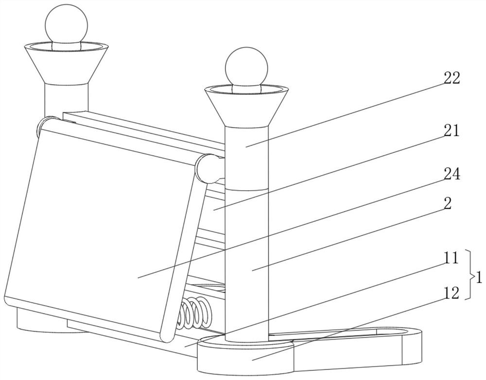
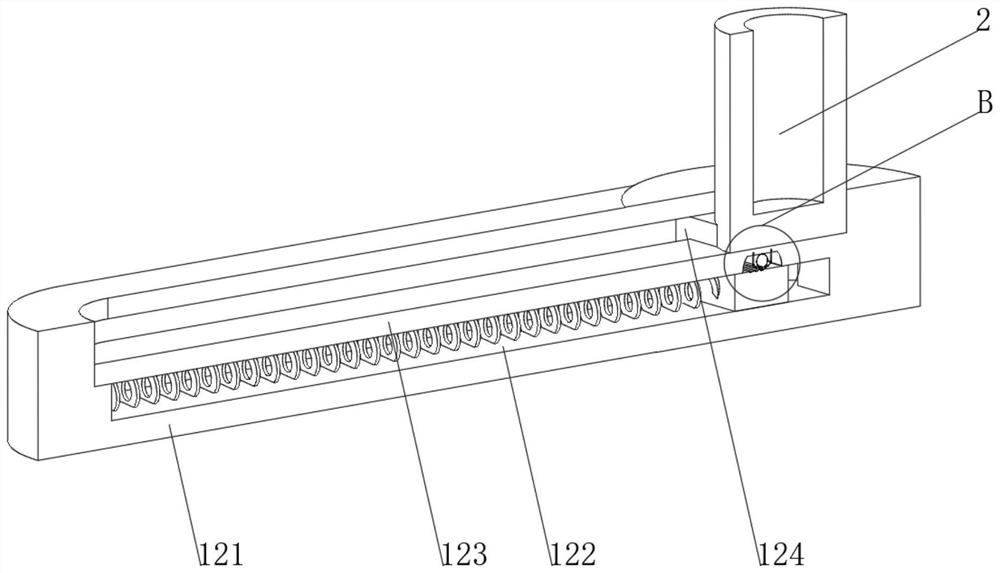
[0037] see Figure 1-3 , the present invention provides a technical solution: a bridge guardrail, specifically comprising: a fixed base 1, the fixed base 1 has a connecting column 11, and a sliding base 12 fixed at both ends of the connecting column, the sliding base 12 is symmetrical about the center of the connecting column 11 set up;
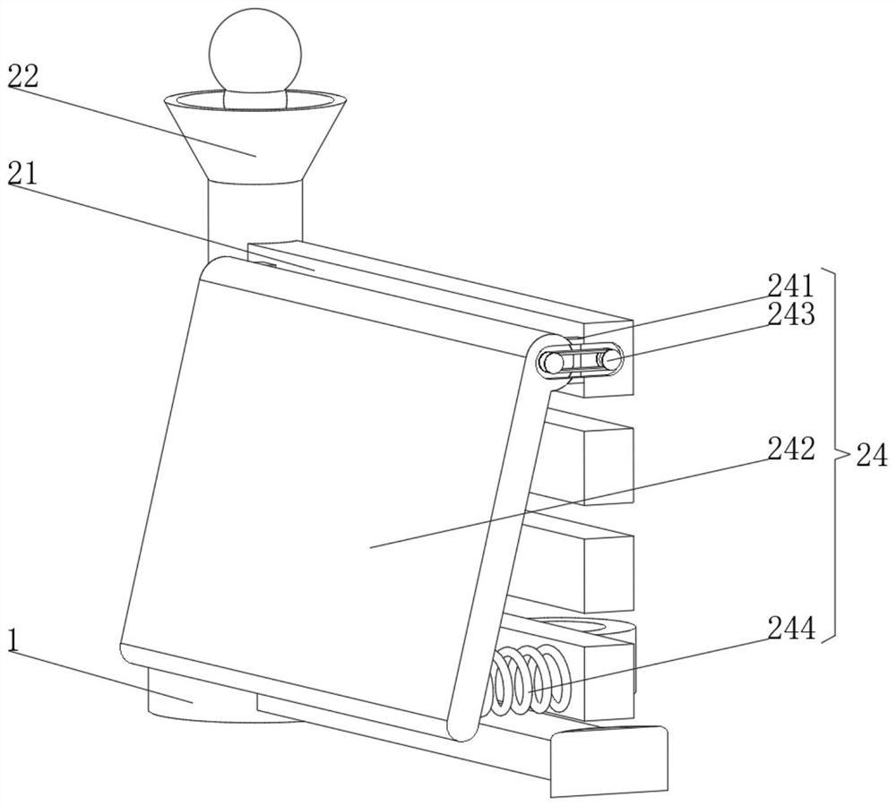
[0038] Guardrail column 2, this guardrail column 2 is arranged on the inside of the sliding base 12 and can slide inside the sliding base 12, the top of the guardrail column 2 is provided with a warning light 22, and one side of the guardrail column 2 is fixed with a fixed column 21, and the fixed column 21 is provided with Several groups are evenly distributed on one side of the guardrail column 2, and a rotation buffer device 24 is arranged on the side of the fixed column 21;
[0039] The rotation buffer device 24 has:
[0040] Rotating seat 241, this rotating seat 241 side is provided with buffer plate 242, and buffer plate 242 can rotat...
Embodiment 2
[0044] see Figure 1-5 , on the basis of Embodiment 1, the present invention provides a technical solution: the above-mentioned warning light 22 can be replaced by a warning light device 220, and the warning light device 220 includes a lamp tube 221, and a limit ring 222 is arranged inside the lamp tube 221. The inner wall of the ring 222 is slidably connected with a telescopic rod 223, and the telescopic rod 223 can slide on the inner wall of the limiting ring 222, and the parts of the side of the telescopic rod 223 that are located above and below the limiting ring 222 are fixedly connected with clips that match the limiting ring 222. Ring 224, the bottom of the telescopic rod 223 is provided with a first magnet block 225, the side of the lamp tube 221 below the first magnet block 225 runs through a rotating rod 226, and one end of the rotating rod 226 located inside the lamp tube 221 is fixedly connected with a second magnet block 227;
[0045] The bottom of the lamp tube ...
Embodiment 3
[0049] see Figure 1-6 , on the basis of Embodiment 1 and Embodiment 2, the present invention provides a technical solution: a control groove 128 is provided at the bottom of the fixed plate 123, a spherical spring 125 is provided at the bottom of the inner wall of the control groove 128, and a control groove 125 is provided at the bottom of the spherical spring 125. Top plate 126, the bottom of the control top plate 126 is provided with a sliding switch piece 127, the part of the inner wall of the sliding sleeve 124 located at the bottom of the control groove 128 is provided with a fixed switch piece 120, and both ends of the control top plate 126 slide through the guide plate 129 and the inner wall of the control groove 128 connect;
[0050] The sliding switch piece 127 is combined with the fixed switch piece 120 to control the opening and closing of the warning light 22, and the fixed switch piece 120 is provided with a plurality of gear positions inside, and different gear...
PUM
 Abstract
Description
Claims
Application Information
 - R&D Engineer
- R&D Manager
- IP Professional
- Industry Leading Data Capabilities
- Powerful AI technology
- Patent DNA Extraction
Browse by: Latest US Patents, China's latest patents, Technical Efficacy Thesaurus, Application Domain, Technology Topic, Popular Technical Reports.
© 2024 PatSnap. All rights reserved.Legal|Privacy policy|Modern Slavery Act Transparency Statement|Sitemap|About US| Contact US: help@patsnap.com


