Eureka AIR delivers breakthrough ideas for toughest innovation challenges, trusted by R&D personnel around the world.

A protective cover base and its safety helmet

A protective cover and helmet technology, which is applied in the direction of helmets, helmet caps, hat products, etc., can solve the problems of inconvenient disassembly, labor and energy consumption, and damage to the helmet, and achieves fast locking and unlocking, simple structural design, and low cost. Effect of Difficulty Factor

Active Publication Date: 2022-03-25
GUANGZHOU JINHAO SPORTING GOODS
View PDF0 Cites 0 Cited by
  • Summary
  • Abstract
  • Description
  • Claims
  • Application Information

AI Technical Summary

Problems solved by technology

[0003] In the prior art, a transparent lens is usually installed in front of the helmet, through which the driver can see the road conditions ahead more clearly, and can also play the role of blocking wind, sand or dust , but the existing lenses can only be firmly fixed on both sides of the helmet, which is very inconvenient to disassemble, so people have designed an unlocking and locking device that can lock the helmet lenses. The existing unlocking and locking devices have some Disadvantages:
[0004] The structure of the existing unlocking and locking device is relatively complicated. The process of locking and unlocking requires a lot of energy and manpower to learn how to operate, which increases the cost of manual operation and learning, and also consumes a lot of manpower and energy, and the operation is very troublesome. Improper operation will cause serious damage to the helmet, causing the helmet to be scrapped

Method used


Image

  • A protective cover base and its safety helmet
  • A protective cover base and its safety helmet
  • A protective cover base and its safety helmet

Examples


Embodiment Construction

[0029] The following will clearly and completely describe the technical solutions in the embodiments of the present invention with reference to the accompanying drawings in the embodiments of the present invention. Obviously, the described embodiments are only some, not all, embodiments of the present invention. Based on the embodiments of the present invention, all other embodiments obtained by persons of ordinary skill in the art without creative efforts fall within the protection scope of the present invention.

[0030] In the description of the present invention, it should be noted that the orientation or positional relationship indicated by the terms "inner", "upper", "lower", "left", "right" etc. is based on the orientation or positional relationship shown in the drawings , is only for the convenience of describing the present invention and simplifying the description, but does not indicate or imply that the referred device or element must have a specific orientation, be ...


PUM


Abstract

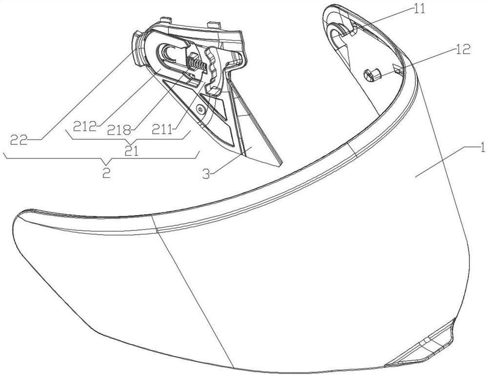
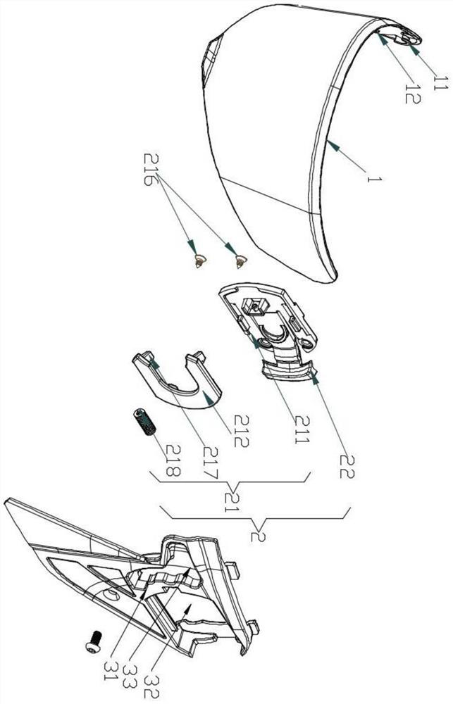
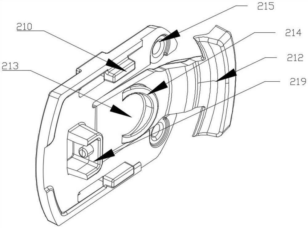
The invention discloses a protective cover base and a safety helmet thereof. The protective cover base includes a protective mirror mechanism and a locking mechanism, and the protective mirror mechanism is fastened to the locking mechanism. The inner walls on both sides of the protective mirror mechanism are formed with The lens protrudes, and the locking mechanism includes a sliding lock groove assembly and an unlocking projection, the unlocking projection is connected to the end of the sliding lock groove assembly, and the locking mechanism locks the protective mirror mechanism by hooking the lens projection through the sliding lock groove assembly , so as to realize the locking of the protective mirror mechanism; press down the unlocking projection to move the sliding lock groove assembly downward, so that the lens protrusion can be separated from the sliding lock groove assembly, thereby realizing the unlocking of the protective mirror mechanism, and the protective mirror mechanism faces outward Pulling can also make the lens protrusion out of the position of the sliding lock groove assembly, so as to realize the disassembly of the protective mirror mechanism. During the whole operation process, there is no need to waste energy and cost to teach people to operate, and reduce cost input.

Description

technical field [0001] The invention relates to the technical field of helmets, in particular to a protective cover base and a safety helmet thereof. Background technique [0002] A helmet is a protective gear used to protect the head, and it is an indispensable tool in people's traffic. Especially when driving a motorcycle, it is very important to wear a helmet. [0003] In the prior art, a transparent lens is usually installed in front of the helmet. Through this transparent lens, the driver can see the road conditions ahead more clearly, and it can also play the role of blocking wind, sand or dust. , but the existing lenses can only be firmly fixed on both sides of the helmet, which is very inconvenient to disassemble, so people have designed an unlocking and locking device that can lock the helmet lenses. The existing unlocking and locking devices have some Disadvantages: [0004] The structure of the existing unlocking and locking device is relatively complicated. The...

Claims


Application Information

Patent Timeline
Patent Type & Authority Patents(China)
IPC IPC(8): A42B3/22
CPCA42B3/221
Inventor 陈嘉辉
Owner GUANGZHOU JINHAO SPORTING GOODS
Why Eureka
Eureka Blog
Learn More