
Automatic smearing and rotating equipment for round cakes

A technology for rotating equipment and cakes, which is applied to cleaning methods and utensils, chemical instruments and methods, and cleaning methods using tools, etc., can solve the problems of inability to limit the position of cakes and automatic cleaning of smear blades, and achieve the effect of simple operation.

Active Publication Date: 2021-10-12
GANZHOU LIANGHUA FEIER SNOW FOOD CO LTD
View PDF24 Cites 3 Cited by
  • Summary
  • Abstract
  • Description
  • Claims
  • Application Information

AI Technical Summary

Problems solved by technology

[0004] In order to overcome the shortcomings of the existing equipment, which cannot automatically clean the smear scraper and limit the effect of the cake, the technical problem of the present invention is: to provide a circle that can realize automatic cleaning of the smear scraper and limit the cake. Shaped cake automatic spreader rotating equipment

Method used


Image

  • Automatic smearing and rotating equipment for round cakes
  • Automatic smearing and rotating equipment for round cakes
  • Automatic smearing and rotating equipment for round cakes

Examples


Embodiment 1

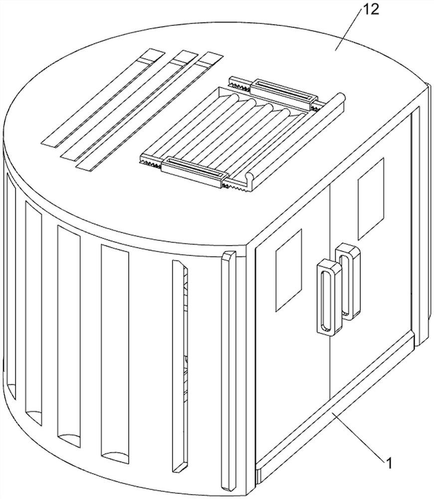
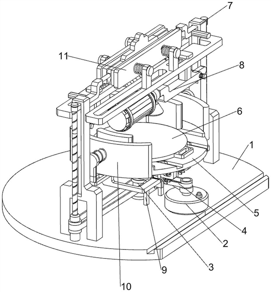
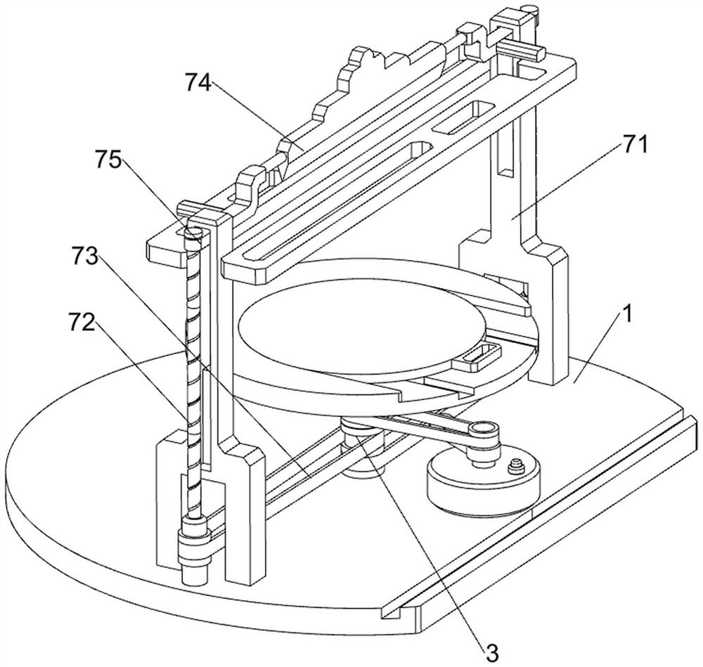
[0028] A round cake automatic spreading rotating equipment, such as Figure 1-5 As shown, it includes a base plate 1, a motor 2, a first rotating shaft 3, a first belt 4, a turntable 5, a movable plate 6, a scraping mechanism 7 and a material spraying mechanism 8, and a motor 2 is arranged in the middle of the right side of the base plate 1, and the base plate 1 The middle rotating shaft 3 is connected with the first rotating shaft, the first belt 4 is wound between the middle of the first rotating shaft 3 and the output shaft of the motor 2, the top of the first rotating shaft 3 is provided with a turntable 5, and the top of the turntable 5 is slidingly connected with a movable disc 6, The bottom plate 1 is provided with a scraping mechanism 7, and the scraping mechanism 7 is provided with a spraying mechanism 8.

[0029] The scraping mechanism 7 includes a support frame 71, a screw mandrel 72, a second belt 73, a first movable plate 74, a first movable block 75, a second mov...

Embodiment 2

[0033] On the basis of Example 1, such as Figure 6-10 Shown, also include clamping mechanism 9, clamping mechanism 9 first support column 91, first movable frame 92, the 3rd compression spring 93, the second support column 94, the second movable frame 95 and the 4th compression spring 96 , the front and rear sides of the bottom right side of the turntable 5 are connected with the first support column 91, the first movable frame 92 is slidably connected between the first support columns 91, the first movable frame 92 is slidably connected with the turntable 5, the first movable A third compression spring 93 is provided between the front and rear sides of the upper part of the frame 92 and the first support column 91, and a second support column 94 is connected to the front and rear sides of the right part of the base plate 1, and a sliding connection is made between the second support columns 94. The second movable frame 95, the motor 2 output shaft bottom is provided with a d...


PUM


Abstract

The invention relates to rotating equipment, and in particular relates to automatic smearing and rotating equipment for round cakes. The technical problem of the invention is to provide the automatic smearing and rotating equipment for round cakes, and the equipment can realize automatic cleaning of a smearing scraping blade and limiting of the cakes. According to the technical scheme, the automatic smearing and rotating equipment for round cakes comprises a bottom plate, a motor, a first rotating shaft, a first belt, a rotating disc and a movable disc, the motor is arranged in the middle of one side of the bottom plate, the first rotating shaft is rotationally connected to the middle of the bottom plate, the first belt is wound between the middle of the first rotating shaft and an output shaft of the motor, the rotating disc is arranged at the top of the first rotating shaft, and the top of the rotating disc is slidably connected with a movable disc. Through cooperation of a material scraping mechanism and a material spraying mechanism, cream can be automatically sprayed to a cake, meanwhile, the cream can be evenly smeared to the cake, and operation is easy.

Description

technical field [0001] The invention relates to a rotating device, in particular to a circular cake automatic spreading rotating device. Background technique [0002] Patent application CN201611246150.6 A circular cake automatic spreading rotation mechanism, including a frame, the frame includes two vertical support plates, the middle plate is fixed in the middle of the two vertical support plates, the top of the middle plate The cake installation seat is fixed in the middle of the surface, and the cake to be processed is placed on the top surface of the cake installation seat; the upper connecting plate is fixed on the top of the two vertical support plates, and the bottom surface of the middle part of the upper connecting plate is hinged with a smearing pressure plate, and the two sides of the bottom surface of the smearing pressure plate are Side support plates are fixed, and the two ends of the transverse transmission screw are hinged on the two side support plates, and ...

Claims


Application Information

Patent Timeline
Patent Type & Authority Applications(China)
IPC IPC(8): A21C15/00B08B1/02B08B17/04B08B1/20
CPCA21C15/002B08B17/04B08B1/165B08B1/20Y02P70/10
Inventor 曾亮生
Owner GANZHOU LIANGHUA FEIER SNOW FOOD CO LTD
Learn More