A kind of backrest type fiber preparation tank
A back-to-back fiber technology, which is applied in fiber processing, textiles and papermaking, filament/thread forming, etc., can solve the problems that back-to-back fibers cannot be produced, and achieve the effect of easy operation and high efficiency
- Summary
- Abstract
- Description
- Claims
- Application Information
AI Technical Summary
Problems solved by technology
Method used
Image

Examples
Embodiment 1
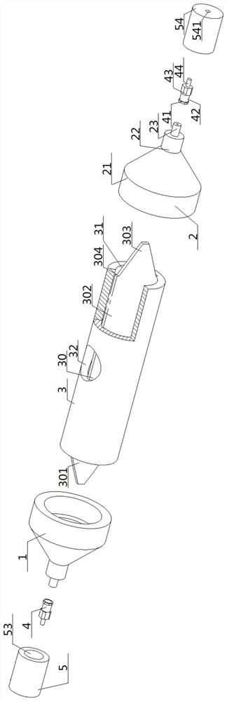
[0057] see figure 1 — Figure 7 , a backrest type fiber production tank, comprising a tank body 3, a left nozzle 1 and a right nozzle 2, the tank body 3 is a cylindrical structure, the inside of the tank body 3 is provided with a coaxial tank column cavity 31, the tank body 3 is provided with a liquid inlet hole 32 communicating with the tank column cavity 31, and a partition plate 30 is jammed inside the tank column cavity 31. The partition plate 30 includes a left corner plate 301 and a middle plate 302 connected in sequence. , the right corner plate 303, the middle plate 302 is located inside the tank column cavity 31, the tank column cavity 31 is divided into the tank column front cavity 311 and the tank column rear cavity 312 by the middle plate 302, the front of the middle plate 302 and the tank column front cavity 311, the back of the middle plate 302 is in contact with the rear chamber 312 of the tank column, and the top and bottom of the middle plate 302 are in conta...
Embodiment 2
[0059] Basic content is the same as embodiment 1, the difference is:
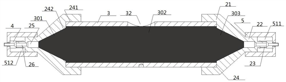
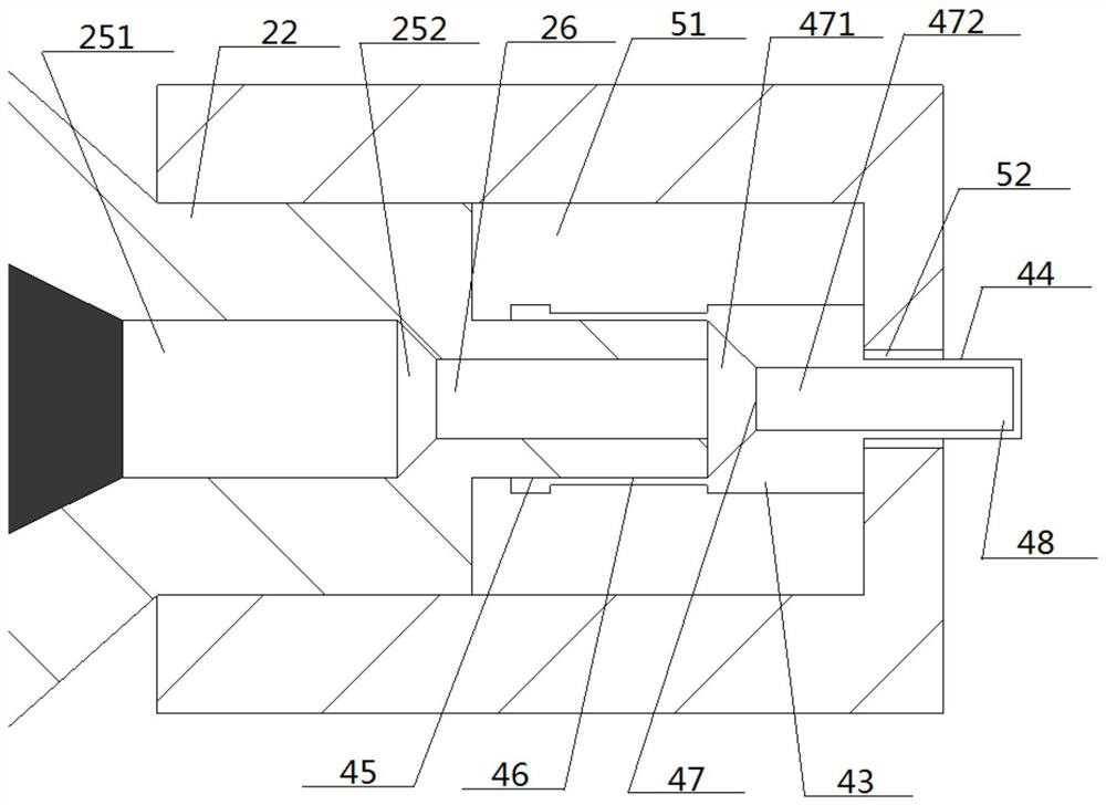
[0060] The rear mouth cavity 24 includes a rear mouth column cavity 241 and a rear mouth cone cavity 242, the rear mouth column cavity 241 is sleeved on the outer side of the end of the tank body 3, and the rear mouth cone cavity 242 covers the corresponding The outside of the left corner plate 301 or the right corner plate 303; the large diameter end of the rear mouth cone cavity 242 communicates with the rear mouth column cavity 241, and the small diameter end of the rear mouth cone cavity 242 is flush with the middle mouth cavity 25, And the diameter of the middle mouth cavity 25 is greater than the thickness of the left corner plate 301 and the right corner plate 303 . The middle mouth cavity 25 includes a middle mouth rear cavity 251 and a middle mouth front cavity 252, the middle mouth rear cavity 251 is a cylindrical structure, the middle mouth front cavity 252 is a truncated cone structure, and the ...
Embodiment 3
[0062] Basic content is the same as embodiment 1, the difference is:
[0063]Two needle tubes 4 are added, and a single needle tube 4 corresponds to the left nozzle 1 or the right nozzle 2; the needle tube 4 includes a needle tube seat section 41, a needle tube waist section 42, a needle tube head section 43 and a needle tube The tip section 44, the needle tube seat section 41, the needle tube waist section 42, the needle tube head section 43, and the needle tube tip section 44 are correspondingly provided with a needle tube seat cavity 45, a needle tube waist cavity 46, a needle tube head cavity 47, Needle tube tip cavity 48; the needle tube seat cavity 45 and the needle tube waist cavity 46 are all sleeved on the outer circumference of the front post mouth 23, and the needle tube head section 43 and the needle tube tip section 44 all extend in a direction away from the front post mouth 23 . The needle tube head cavity 47 includes a needle tube conical head cavity 471 and a ...
PUM
 Abstract
Description
Claims
Application Information
 - R&D
- Intellectual Property
- Life Sciences
- Materials
- Tech Scout
- Unparalleled Data Quality
- Higher Quality Content
- 60% Fewer Hallucinations
Browse by: Latest US Patents, China's latest patents, Technical Efficacy Thesaurus, Application Domain, Technology Topic, Popular Technical Reports.
© 2025 PatSnap. All rights reserved.Legal|Privacy policy|Modern Slavery Act Transparency Statement|Sitemap|About US| Contact US: help@patsnap.com