
Strength testing device for radar part production and processing

A technology for strength testing and parts, which is applied in the field of strength testing devices for the production and processing of radar parts, can solve the problems of a lot of time, low efficiency, time-consuming and laborious, etc., and achieve the effect of increasing tightness and improving stability

Inactive Publication Date: 2021-10-08
DONGGUAN UNIV OF TECH
View PDF0 Cites 1 Cited by
  • Summary
  • Abstract
  • Description
  • Claims
  • Application Information

AI Technical Summary

Problems solved by technology

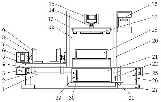
[0004] Aiming at the deficiencies of the prior art, the present invention provides a strength testing device for the production and processing of radar parts, which solves the problem that the existing strength testing device for the production and processing of radar parts proposed in the above background technology needs to be manually fixed on the In the inspection box, after the inspection is completed, it needs to be manually taken out and transferred, which is time-consuming and labor-intensive, and the existing radar component strength test device can only test its strength, and it will take a lot of time to separate the qualified products from the defective products. Picking, the problem of low efficiency

Method used


Image

  • Strength testing device for radar part production and processing
  • Strength testing device for radar part production and processing
  • Strength testing device for radar part production and processing

Examples


Embodiment Construction

[0028] The following will clearly and completely describe the technical solutions in the embodiments of the present invention with reference to the accompanying drawings in the embodiments of the present invention. Obviously, the described embodiments are only some, not all, embodiments of the present invention.

[0029] In the description of the present invention, unless otherwise stated, the meaning of "plurality" is two or more; the terms "upper", "lower", "left", "right", "inner", "outer" , "front end", "rear end", "head", "tail", etc. indicate the orientation or positional relationship based on the orientation or positional relationship shown in the drawings, and are only for the convenience of describing the present invention and simplifying the description, rather than Indicates or implies that the device or element referred to must have a particular orientation, be constructed and operate in a particular orientation, and therefore should not be construed as limiting the...


PUM


Abstract

The invention discloses a strength testing device for radar part production and processing, and relates to the technical field of testing devices, in particular to a strength testing device for radar part production and processing. The strength testing device comprises a base, a conveying platform and a strength testing box, a servo motor is mounted in the interior of the base, a ball screw is mounted on the right side of the servo motor, the strength testing box is mounted on the right side of the conveying platform, a placement platform is mounted at the front end of the base, a defective product collecting box is arranged above the placement platform, an iron patch is connected to the rear end of the defective product collecting box, and a magnet patch is mounted at the rear end of the iron patch. According to the strength testing device for radar part production and processing, the defective product collecting box is arranged so that defective product parts can be conveniently collected, the placement platform facilitates placement of the defective product collecting box, attraction can be carried out on the defective product collecting box and the base through the magnet patch and the iron patch, and therefore the defective product collection box can be taken and placed conveniently.

Description

technical field [0001] The invention relates to the technical field of production and processing of radar parts, in particular to a strength testing device for production and processing of radar parts. Background technique [0002] Radar is an electronic device that uses electromagnetic waves to detect targets. It is called "radio positioning". It uses radio methods to find targets and determine their spatial positions. Radar emits electromagnetic waves to illuminate targets and receive their echoes, thereby obtaining targets. The distance to the electromagnetic wave emission point, the distance change rate (radial velocity), azimuth, height and other information need to be tested for strength during the production and processing of radar parts. Only after the test is qualified can they be used in the factory, so it is necessary to To the strength test device for the production and processing of radar parts. [0003] The existing strength testing device for the production a...

Claims


Application Information

Patent Timeline
Patent Type & Authority Applications(China)
IPC IPC(8): B07C5/02B07C5/34B07C5/36B07C5/38
CPCB07C5/02B07C5/34B07C5/362B07C5/38
Inventor 邓凯张佳宇彭达
Owner DONGGUAN UNIV OF TECH
Learn More