Dynamic centering method of vibration system under vibration condition

A vibration system and dynamic technology, applied in vibration testing, machine/structural component testing, measuring devices, etc., can solve problems such as floating or sinking of the moving coil, affecting test quality, failures, etc., to achieve automatic dynamic control, The effect of simple overall structure and convenient control

Pending Publication Date: 2021-10-01
SUZHOU SUSHI TESTING INSTR CO LTD
View PDF9 Cites 1 Cited by
  • Summary
  • Abstract
  • Description
  • Claims
  • Application Information

AI Technical Summary

Problems solved by technology

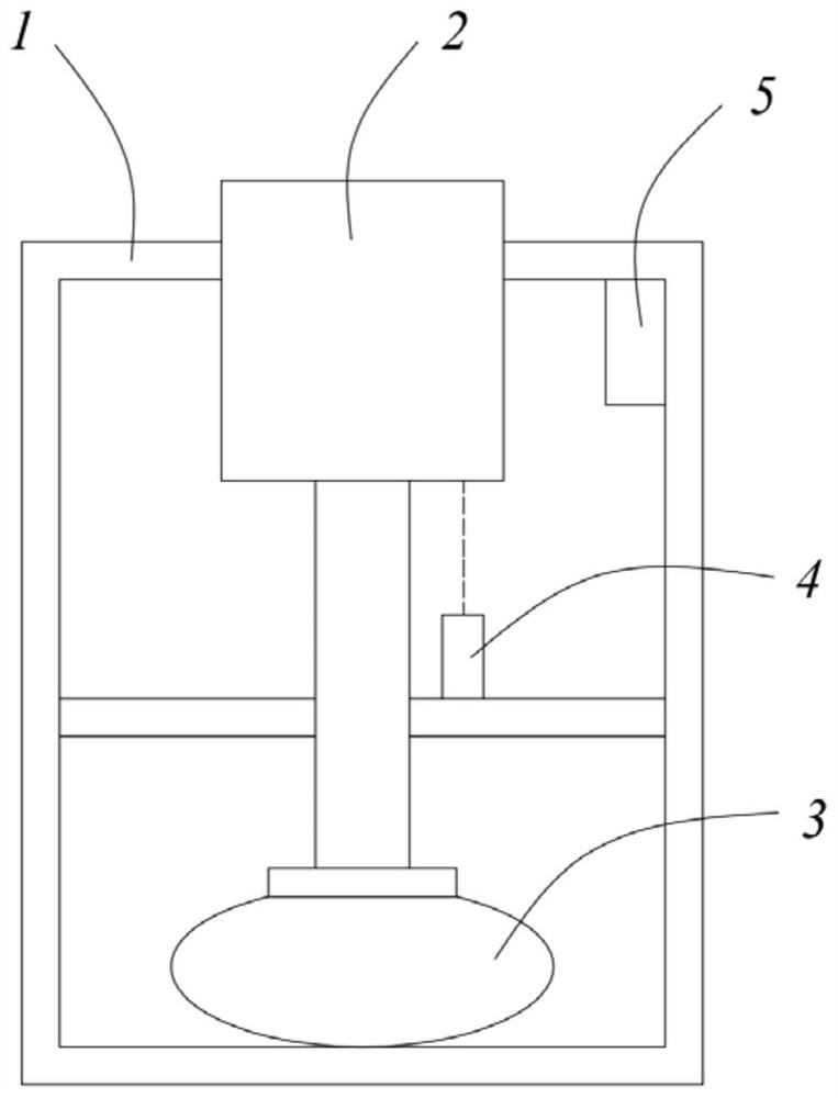
[0003] The electric vibration table is mainly composed of a table body, a moving coil and an air bag at the bottom of the moving coil. The moving coil reciprocates relative to the table body, and the air bag has a supporting effect; when performing a vibration test, the force of the table body is easily affected by external factors. Influence, such as the quality of the test body, the external air pressure and other factors, and the air pressure in the airbag has not changed at this time, which will cause the moving coil to float or sink, so that the center position of the moving coil will change during the test, ranging from It cannot simulate the real stress environment of the test body, which will affect the quality of the test. If it is heavy, it will cause damage to the test body and malfunction

Method used


Image

  • Dynamic centering method of vibration system under vibration condition
  • Dynamic centering method of vibration system under vibration condition
  • Dynamic centering method of vibration system under vibration condition

Examples


Embodiment Construction

[0028] The technical solutions of the present invention will be clearly and completely described below in conjunction with the accompanying drawings. Apparently, the described embodiments are some of the embodiments of the present invention, but not all of them. Based on the embodiments of the present invention, all other embodiments obtained by persons of ordinary skill in the art without making creative efforts belong to the protection scope of the present invention.

[0029] In the description of the present invention, it should be noted that the terms "center", "upper", "lower", "left", "right", "vertical", "horizontal", "inner", "outer" etc. The indicated orientation or positional relationship is based on the orientation or positional relationship shown in the drawings, and is only for the convenience of describing the present invention and simplifying the description, rather than indicating or implying that the referred device or element must have a specific orientation, ...


PUM


Abstract

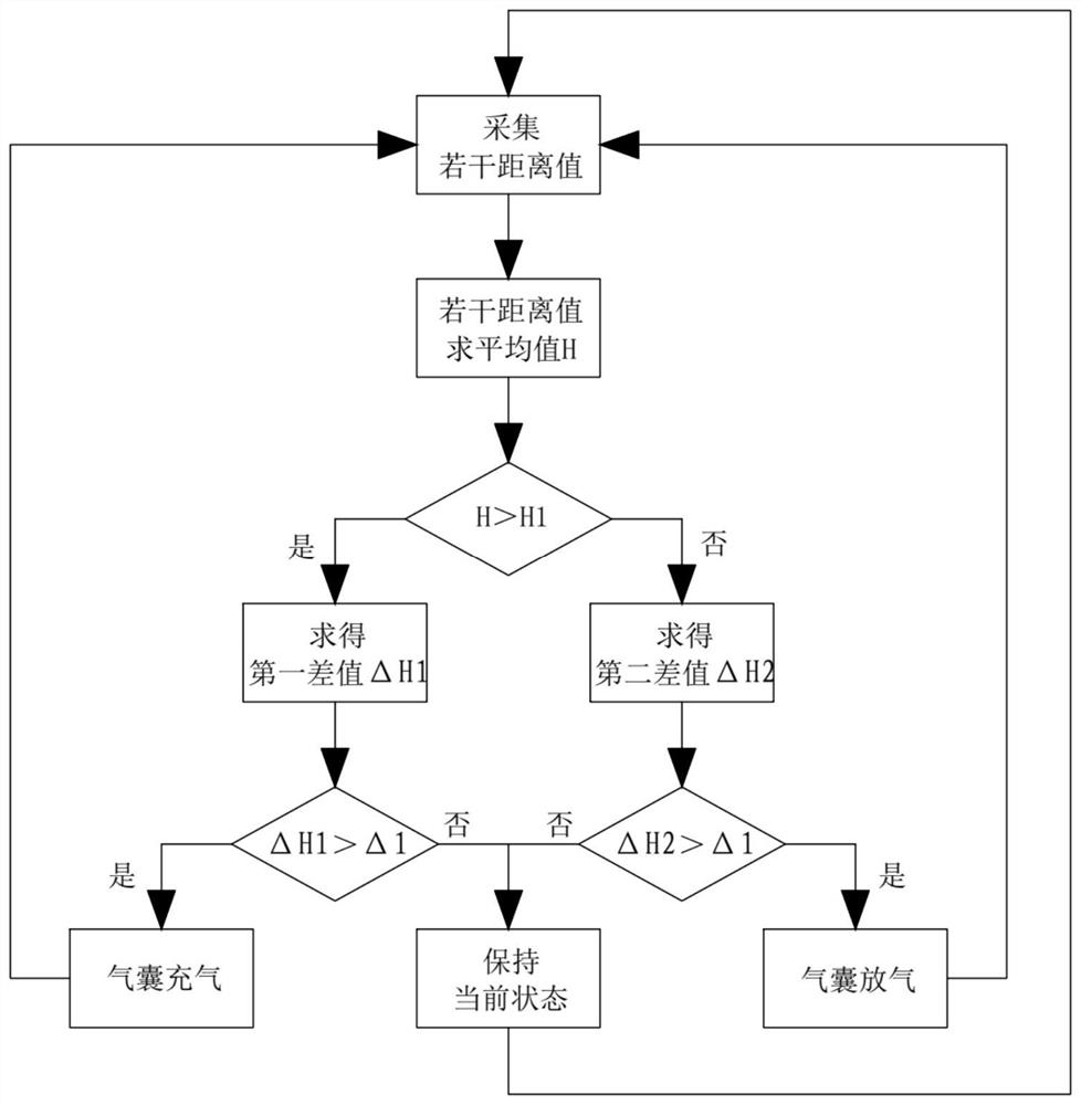
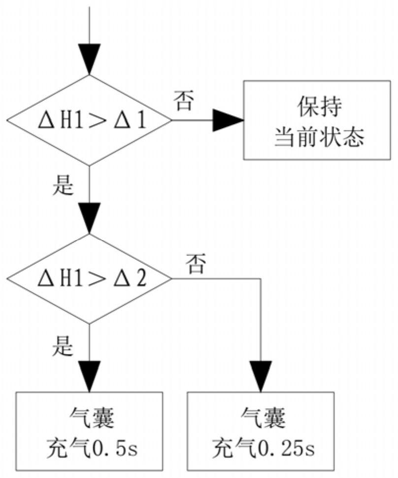
The invention relates to a dynamic centering method of a vibration system under a vibration condition. The method comprises the following steps: S1, enabling a distance measuring module to measure the distance between a moving coil and the distance measuring module for multiple times and transmit the distance to a control module; S2, solving an average value of a plurality of distances; S3, judging whether the average value is greater than the centering value or not, if so, entering step S4, and if not, entering step S5; S4, judging whether the first difference value is greater than a first error value, if so, deflating the air bag, and if not, keeping the current state; S5, judging whether the second difference value is larger than the first error value or not, if yes, inflating the air bag, and if not, keeping the current state. Through the method, the operation on the air bag is determined according to the judgment on the difference value, the position of the centering state is adjusted by inflating or deflating the air bag, the inaccurate centering state caused by the influence of external factors is corrected, the overall structure is simple, the control is convenient, the centering effect cannot be influenced even if the air bag inclines, meanwhile, the precision is high, and automatic dynamic control is realized.

Description

technical field [0001] The invention relates to the technical field of vibration tests, in particular to a dynamic centering method of a vibration system under vibration conditions. Background technique [0002] The electric vibration table can simulate various vibration dynamic environments, and is widely used in simulation tests of various typical vibrations such as auto parts, electronic components, and stress screening of aerospace products. [0003] The electric vibration table is mainly composed of a table body, a moving coil and an air bag at the bottom of the moving coil. The moving coil reciprocates relative to the table body, and the air bag has a supporting effect; when performing a vibration test, the force of the table body is easily affected by external factors. Influence, such as the quality of the test body, the external air pressure and other factors, and the air pressure in the airbag has not changed at this time, which will cause the moving coil to float o...

Claims


Application Information

Patent Timeline
Patent Type & Authority Applications(China)
IPC IPC(8): G01M7/02
CPCG01M7/02
Inventor 盛九朝
Owner SUZHOU SUSHI TESTING INSTR CO LTD
Why Eureka
Try Eureka