Water surface garbage cleaning device

A technology of cleaning device and water surface garbage, which is applied in the direction of open water surface cleaning, water conservancy engineering, filtration and separation, etc., can solve problems such as inability to achieve water and filtration, reduce work intensity, increase collection and storage capacity, and strengthen sundry storage capacity. Effect

Inactive Publication Date: 2021-10-01
何钧健
View PDF1 Cites 2 Cited by
  • Summary
  • Abstract
  • Description
  • Claims
  • Application Information

AI Technical Summary

Problems solved by technology

[0006] Aiming at the deficiencies of the prior art, the present invention provides a water surface garbage cleaning device, which solves the problem that the device cannot filter water when collecting water surface garbage, so that debris remains in the collection frame, and excess water It is squeezed out of the device, which strengthens the storage capacity of the device, improves the practicality, achieves the purpose of rolling the collected debris, further increases the storage capacity of the device, and improves the collection efficiency

Method used


Image

  • Water surface garbage cleaning device
  • Water surface garbage cleaning device
  • Water surface garbage cleaning device

Examples


Embodiment 1

[0029] see Figure 1-5 , the present invention provides a technical solution: a water surface garbage cleaning device, comprising a housing 1, the bottom of the housing 1 is fixedly connected with a filter 2, and the side of the filter 2 away from the housing 1 is fixedly connected with a collection frame 3, and the outer side of the housing 1 A foam floating plate 4 is evenly installed at a position away from the collection frame 3, and a telescopic cylinder 5 is installed outside the bottom of the collection frame 3. The piston rod of the telescopic cylinder 5 is fixedly connected with a telescopic rod 6, and the end of the telescopic rod 6 far away from the telescopic cylinder 5 runs through the collection The frame 3 is fixedly connected with a fixed block 7, the bottom of the collecting frame 3 is evenly provided with a water outlet 8 near the telescopic cylinder 5, and the inner wall of the shell 1 is fixedly connected with a suction device 9.

[0030] The bottom of the ...

Embodiment 2

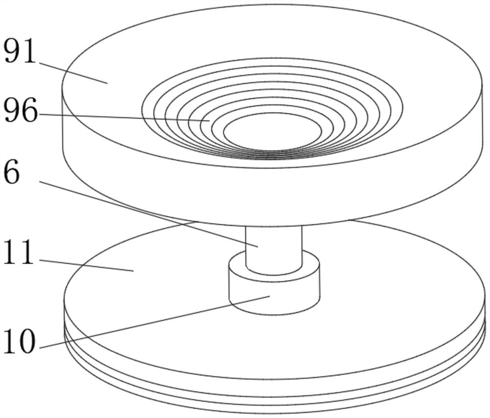
[0035] see Figure 1-6 , the present invention provides a technical solution: on the basis of Embodiment 1, a rubber sealing ring 10 is installed on the outside of the telescopic rod 6 away from the fixed block 7, and an extrusion device 11 is fixedly connected to the outside of the rubber sealing ring 10.

[0036] The extruding device 11 includes a circular extruding frame 111, the inner side of the circular extruding frame 111 is fixedly connected with the rubber sealing ring 10, and one side of the circular extruding frame 111 is uniformly provided with a water outlet 112, and the circular extruding frame 111 A mounting block 113 is fixedly connected to a side close to the water outlet 112 , and a cylindrical stopper 114 is fixedly connected to a side of the mounting block 113 away from the water outlet 112 .

[0037] The bottom of the circular extruding frame 111 is symmetrically provided with a groove 15, the inner wall of the groove 15 is rotatably connected with a rotat...


PUM


Abstract

The invention discloses a water surface garbage cleaning device, and relates to the technical field of environmental protection. The water surface garbage cleaning device comprises a shell, wherein a filter screen is fixedly connected to the bottom of the shell; a collecting frame is fixedly connected to the side, away from the shell, of the filter screen; foam floating plates are evenly installed at the position, away from the collecting frame, of the outer side of the shell; a telescopic air cylinder is installed on the outer side of the bottom of the collecting frame; a piston rod of the telescopic air cylinder is fixedly connected with a telescopic rod; the end, away from the telescopic air cylinder, of the telescopic rod penetrates the collecting frame to be fixedly connected with a fixing block; water outlets are evenly formed in the position, close to the telescopic air cylinder, of the bottom of the collecting frame; a material suction device is fixedly connected to the inner wall of the shell; and a rubber sealing ring is installed at the position, away from the fixing block, of the outer side of the telescopic rod. According to the water surface garbage cleaning device, the aim of collecting floating objects on the water flow surface is achieved, the work intensity of environmental protection persons is reduced, and the device is suitable for small river water areas, and is flexible and light.

Description

technical field [0001] The invention relates to the technical field of environmental protection, in particular to a water surface garbage cleaning device. Background technique [0002] The water surface maintenance of the landscape water body usually includes the cleaning of water surface garbage, such as plastic bags, fallen leaves, duckweed, algae, oil slicks, etc. The cleaning of landscape water body garbage not only involves the aesthetics of the water body, but if it is not cleaned in time, it will further aggravate the deterioration of the water quality. Deterioration, leading to eutrophication of water bodies. Under the current circumstances, the collection of water surface garbage is mainly based on manual salvage, which not only requires more manpower, but also has high labor intensity and low operation efficiency. The existing surface garbage collection ships are mainly aimed at large water areas due to their large size and relatively fixed structure. After being ...

Claims


Application Information

Patent Timeline
Patent Type & Authority Applications(China)
IPC IPC(8): E02B15/10B01D35/02
CPCE02B15/10B01D35/02
Inventor 何钧健
Owner 何钧健
Why Eureka
Try Eureka