Movable plate quick-changing structure and machining equipment

A movable plate and base plate technology, which is applied in metal processing, mechanical equipment, thin plate connection, etc., can solve the problems of time-consuming and labor-consuming, cumbersome disassembly and assembly of the movable plate, and reduce labor intensity, save labor time, and facilitate operation Effect

Pending Publication Date: 2021-10-01
MASTERWORK GROUP CO LTD
View PDF0 Cites 0 Cited by
  • Summary
  • Abstract
  • Description
  • Claims
  • Application Information

AI Technical Summary

Problems solved by technology

[0004] In view of this, in order to overcome the above-mentioned defects, the present invention aims to propose a movable plate quick-change structure and processing equipment to solve the problem that the traditional movable backing plate needs a large number of screws to be fixed to the lower backing plate, causing the movable backing plate to be disassembled. The installation process is cumbersome, time-consuming and labor-intensive

Method used


Image

  • Movable plate quick-changing structure and machining equipment
  • Movable plate quick-changing structure and machining equipment

Examples


Embodiment 1

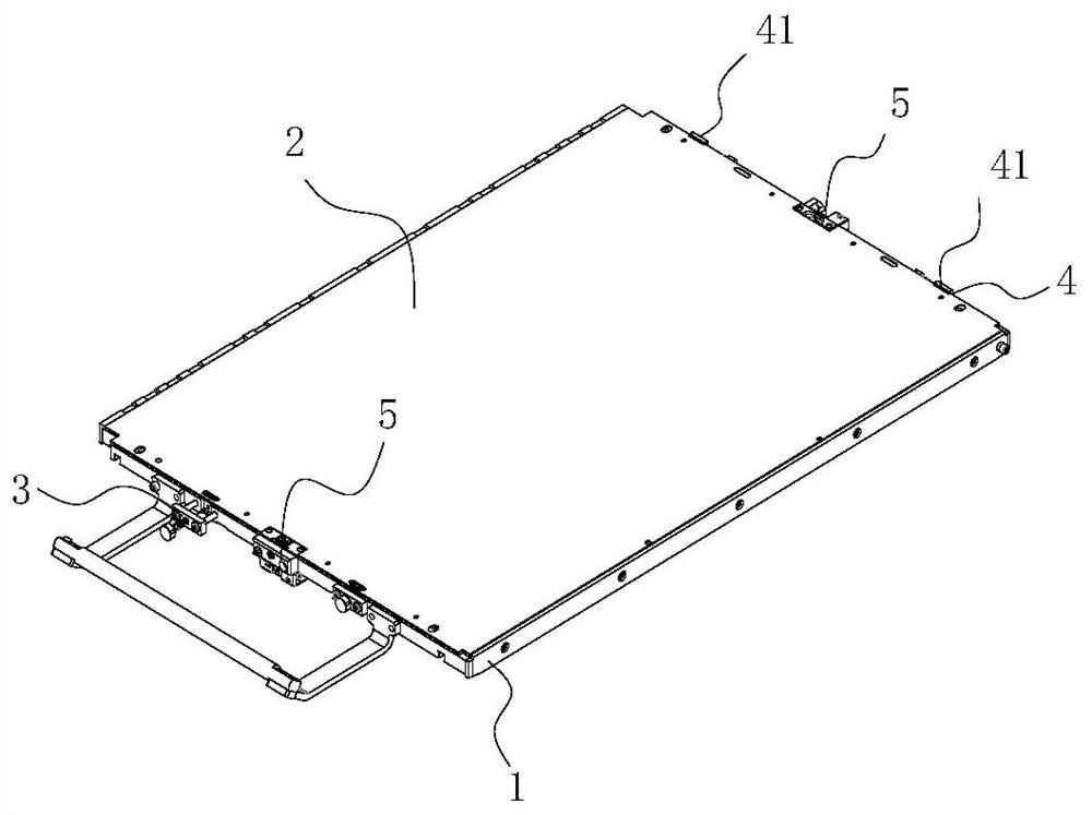
[0032] Such as figure 1 As shown, the present embodiment provides a movable plate quick-change structure for realizing quick disassembly and assembly of the movable plate 2 and the base plate 1, including:

[0033] The limit piece is arranged at one end of the movable plate 2, and is used to limit the position of the end of the movable plate 2;

[0034] The elastic locking member 3 is arranged on the other end of the movable plate 2, and includes an elastic member and a locking member, and the locking member locks the movable plate 2 under the action of the elastic member;

[0035] Both the limiting part and the elastic locking part 3 are installed on the base plate 1 .

[0036] The limiting member is arranged at the tail end of the movable plate 2;

[0037] The movable plate 2 is arranged on the upper surface of the base plate 1, the elastic locking member 3 is arranged at the head end of the movable plate 2, the limiting member is installed at the tail end of the movable p...

Embodiment 2

[0047] The elastic locking member 3 is not limited to the method described in the above-mentioned embodiments, and can also be in the form of an elastic pressing plate, for example, a guide is provided on the side of the substrate 1, the pressing plate is slidably connected to the guiding member, and the elastic member is arranged on the pressing plate in a compressed state. The upper part is used to apply downward elastic force to the pressing plate, so as to realize the pressing and fixing of the movable plate 2.

Embodiment 3

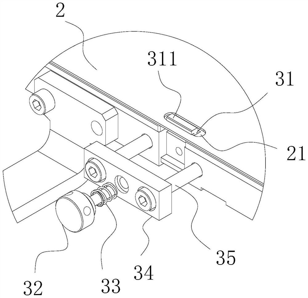
[0049] In addition to the above two methods, the elastic locking member 3 can also adopt the following methods:

[0050] The locking plate 31 is arranged in the slot in a hinged form, one end of the spring 33 abuts against the inner surface of the fixing plate 34, and the other end abuts against the middle and lower side of the locking plate 31, and the spring 33 locks towards the locking plate in a compressed state. The middle and lower sides of the plate 31 apply elastic force, and the bottom of the locking plate 31 moves inwardly and upwardly (because the locking plate 31 is hinged in the slot, the bottom moves in the opposite direction to the upper direction), and the stop hook at the top Two 311 move to the outside to realize the locking of movable plate 2.


PUM


Abstract

The invention provides a movable plate quick-changing structure and machining equipment. The movable plate quick-changing structure is used for realizing quick disassembly and assembly of a movable plate and a base plate, and comprise a limiting piece arranged at one end of the movable plate and used for limiting the end portion position of the movable plate; and an elastic locking piece which is arranged at the other end of the movable plate and comprises an elastic piece and a locking piece, wherein the locking piece locks the movable plate under the action of the elastic piece, and the limiting piece and the elastic locking piece are both installed on the base plate. Compared with the traditional technology, the movable plate quick-changing structure has the advantages that through the quick-changing structure, the labor intensity is reduced, the labor time is saved, and the working efficiency is improved.

Description

technical field [0001] The invention belongs to the field of processing equipment, and in particular relates to a movable plate quick-change structure and processing equipment. Background technique [0002] In the production of sheet-fed die-cutting and hot stamping equipment, in order to meet the needs of different products, such as die-cutting indentation, hot stamping supplementary pressure, etc. It is necessary to paste indentation strips, supplementary pressure plates, etc. on the movable backing plate of the lower backing plate, or directly make or replace the movable backing plate with a steel bottom mold. [0003] When replacing and producing a new product, the movable backing plate in the lower backing plate needs to be replaced according to the product requirements. In the traditional technology, the movable backing plate is fixed to the frame of the lower backing plate by screw locking, and generally 8-10 screws are required. Even more, just can realize the fixin...

Claims


Application Information

Patent Timeline
IPC IPC(8): B26F1/44B26D7/20B26D7/26B41F19/06F16B5/02
CPCB26F1/44B26D7/20B26D7/2614B41F19/06F16B5/0266B26F2001/4418
Inventor 孙炀韦树远刘东李鹏王瑞红
Owner MASTERWORK GROUP CO LTD
Why Eureka
Try Eureka