
Industrial flue gas denitration and desulfurization device

A technology for industrial flue gas and desulfurization devices, applied in gas treatment, membrane technology, and separation of dispersed particles, etc., can solve problems such as increasing environmental pollution, increasing the overall flue gas denitrification and desulfurization time, and reducing denitrification and desulfurization efficiency

Pending Publication Date: 2021-10-01
江苏金盛建设集团有限公司
View PDF13 Cites 2 Cited by
  • Summary
  • Abstract
  • Description
  • Claims
  • Application Information

AI Technical Summary

Problems solved by technology

[0003] The purpose of the present invention is to provide an industrial flue gas denitrification and desulfurization device for the deficiencies of the prior art, so as to solve the problem that the existing flue gas denitrification and desulfurization devices proposed in the above background technology all use fans to transport the flue gas to the denitrification system. In the desulfurization device, the nitrate and sulfur in the flue gas are treated, but the treated flue gas always contains a small amount of carbon dioxide and is discharged into the environment, which not only increases the pollution of the environment but also easily increases the greenhouse effect. At the same time, the existing All the denitrification and desulfurization devices use the same equipment for denitrification and desulfurization, so that the flue gas always contains a small amount of nitrate and sulfur and cannot be completely processed, which in turn causes nitrate and sulfur to be discharged into the environment along with the flue gas, thereby increasing environmental pollution in turn. The probability of acid rain, and the existing denitrification and desulfurization device transports the flue gas inside the equipment because the spraying device is fixed at the same position, resulting in a small amount of flue gas that cannot be denitrified and desulfurized, and also increases the overall flue gas denitrification and desulfurization time. The problem of denitrification and desulfurization efficiency

Method used


Image

  • Industrial flue gas denitration and desulfurization device
  • Industrial flue gas denitration and desulfurization device
  • Industrial flue gas denitration and desulfurization device

Examples


Embodiment Construction

[0027] The following will clearly and completely describe the technical solutions in the embodiments of the present invention with reference to the accompanying drawings in the embodiments of the present invention. Obviously, the described embodiments are only some, not all, embodiments of the present invention. Based on the embodiments of the present invention, all other embodiments obtained by persons of ordinary skill in the art without making creative efforts belong to the protection scope of the present invention.

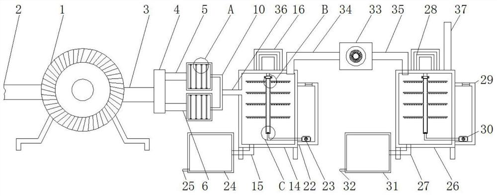
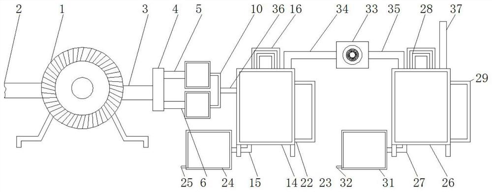
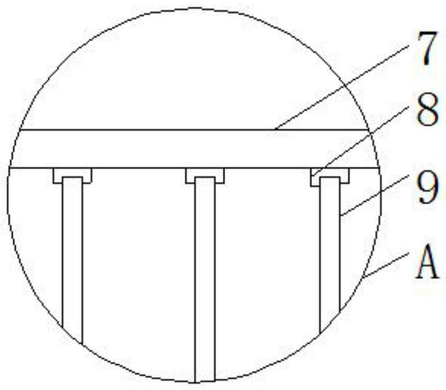
[0028] see Figure 1-6 , the present invention provides a technical solution: an industrial flue gas denitrification and desulfurization device, such as figure 2 , image 3 , Figure 4 and Figure 5As shown, the first suction pipe 2 is embedded and fixed on the left side of the first fan 1, and the first outlet pipe 3 is embedded and fixed on the right side of the first fan 1, and the upper right side of the through frame 4 is embedded and fixed on the lef...


PUM


Abstract

The invention discloses an industrial flue gas denitration and desulfurization device. The device comprises a first fan, a through frame, a filter box group, an activated carbon filter element, a connector group, a desulfurization box, a first rotating motor, a conveying rod, a first conveying pipe, a desulfurizing agent placing box, a first settling box, a denitration box, a second rotating motor, a denitration agent storage box, a second settling box, a second fan, a second conveying pipe and a smoke outlet pipe, a first suction pipe is embedded and fixed to the left side of the first fan, the upper portion of the right side of the through frame is embedded and fixed to the left side of a first through pipe, concave blocks are fixed to the top end and the bottom of the interior of the filter box group, and the activated carbon filter element is clamped and fixed to the interior of the filter box group through the concave blocks. And through the desulfurization box and the denitration box, nitrate and sulfur contain ed in the flue gas can be conveniently and specially removed, so that the situation that the whole steps and procedures are carried out in the same equipment, and meanwhile, the discharged flue gas contains a small amount of nitrate and sulfur is avoided.

Description

technical field [0001] The invention relates to the technical field of industrial flue gas denitrification and desulfurization devices, in particular to an industrial flue gas denitrification and desulfurization device. Background technique [0002] During the combustion process of industrial boilers, the exhausted flue gas often contains sulfur or nitrate. The flue gas pollutants mainly include soot, sulfur dioxide, nitrogen oxides and carbon dioxide, etc., and these are directly discharged into the air to form serious pollution. Sulfur pollution must be curbed , the flue gas must be desulfurized and denitrified, but the existing flue gas denitrification and desulfurization devices transport the flue gas inside the denitrification and desulfurization device through a fan, so that the nitrate and sulfur in the flue gas can be treated, but the treated flue gas The gas always contains a small amount of carbon dioxide and is discharged into the environment, which not only incre...

Claims


Application Information

Patent Timeline
Patent Type & Authority Applications(China)
IPC IPC(8): B01D53/78B01D53/56B01D53/50B01D53/04B01D53/60
CPCB01D53/78B01D53/56B01D53/50B01D53/04B01D53/60B01D2253/102B01D2258/0283
Inventor 还国斌陈书明
Owner 江苏金盛建设集团有限公司
Learn More