
An ear massager for tinnitus rehabilitation treatment

A rehabilitation treatment and ear technology, applied in the field of medical equipment, can solve the problems of poor tinnitus rehabilitation treatment, inability to press, massage effect needs to be improved, etc., to achieve the effect of improving efficiency, improving uniformity, and promoting blood circulation

Active Publication Date: 2022-03-01
SUN YAT SEN MEMORIAL HOSPITAL SUN YAT SEN UNIV
View PDF9 Cites 0 Cited by
  • Summary
  • Abstract
  • Description
  • Claims
  • Application Information

AI Technical Summary

Problems solved by technology

[0006] In order to make up for the deficiencies of the existing technology, most of the ear massagers squeeze the auricle as a whole, and cooperate with vibration to achieve a certain massage effect, but they cannot perform targeted pressing on each acupoint on the auricle. , so the massage effect needs to be improved, and the problem that the treatment effect of tinnitus rehabilitation is poor, the present invention proposes an ear massager for tinnitus rehabilitation treatment

Method used


Image

  • An ear massager for tinnitus rehabilitation treatment
  • An ear massager for tinnitus rehabilitation treatment
  • An ear massager for tinnitus rehabilitation treatment

Examples


Embodiment 1

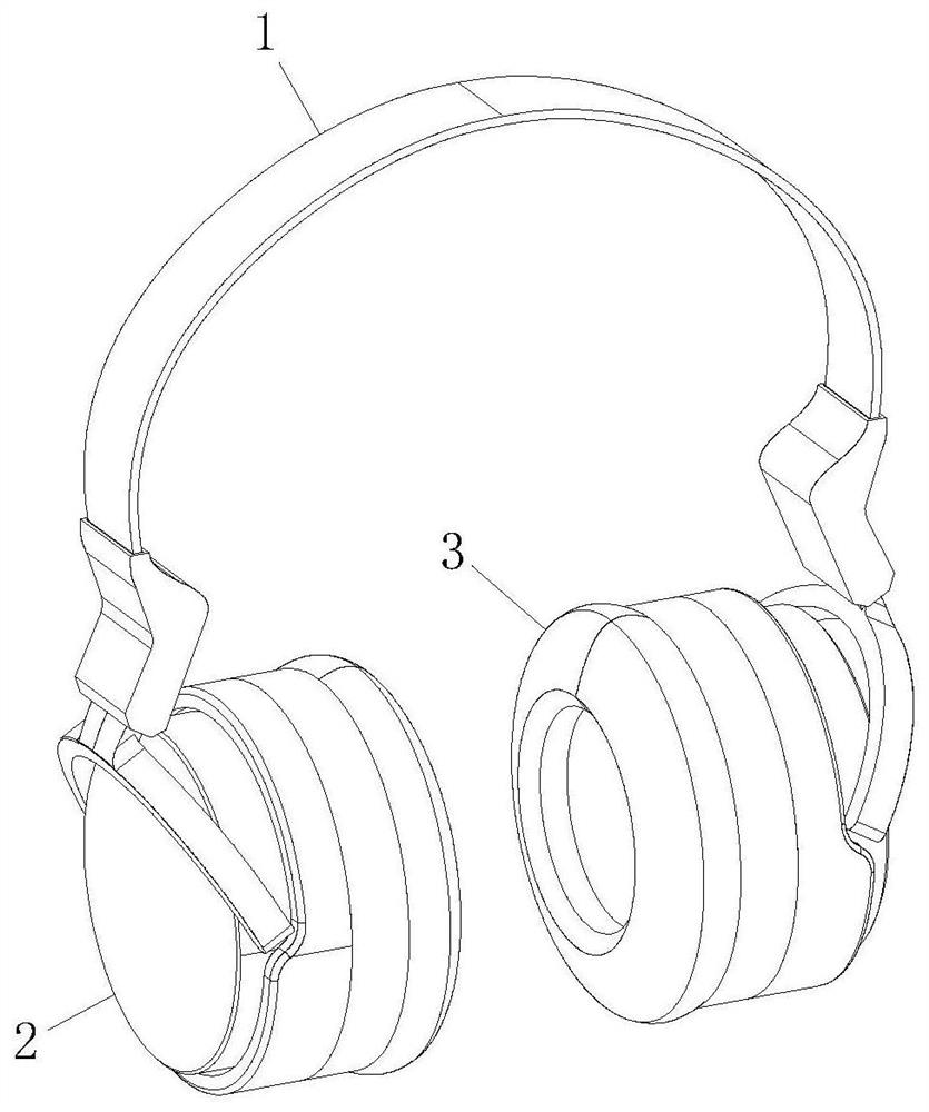
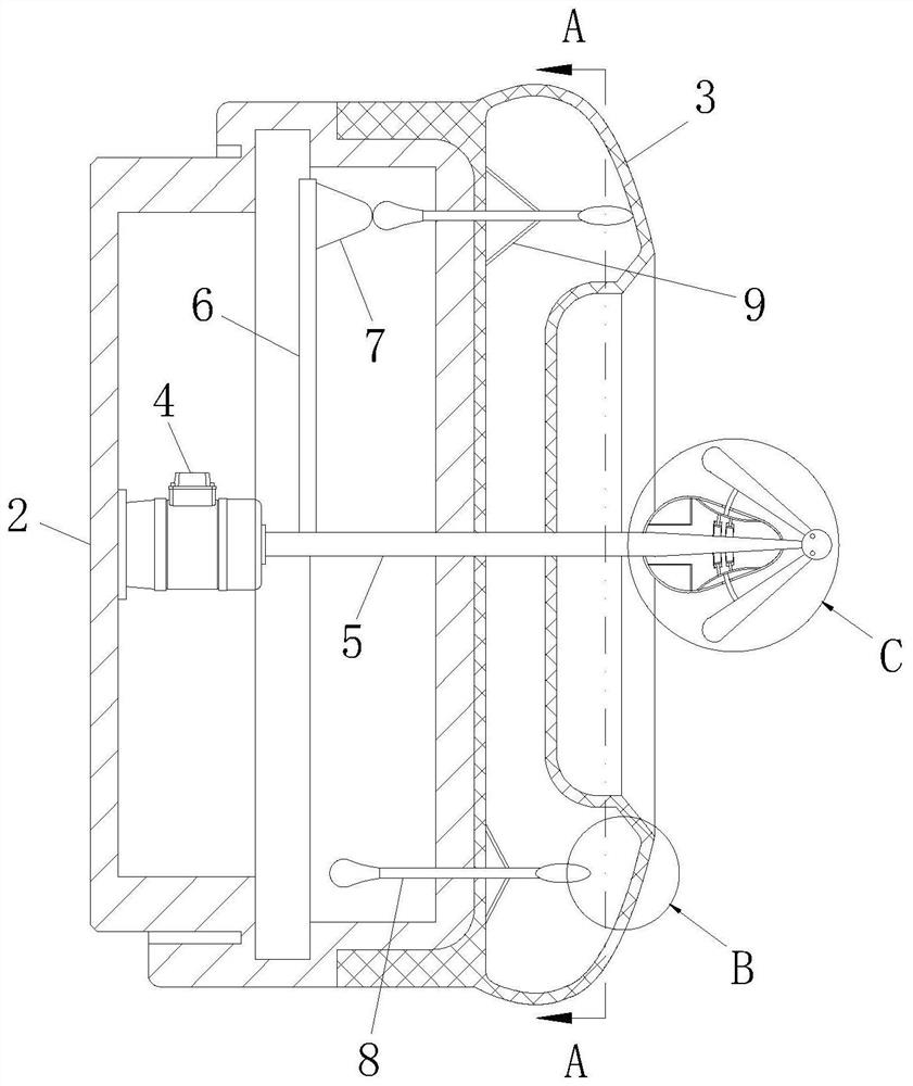
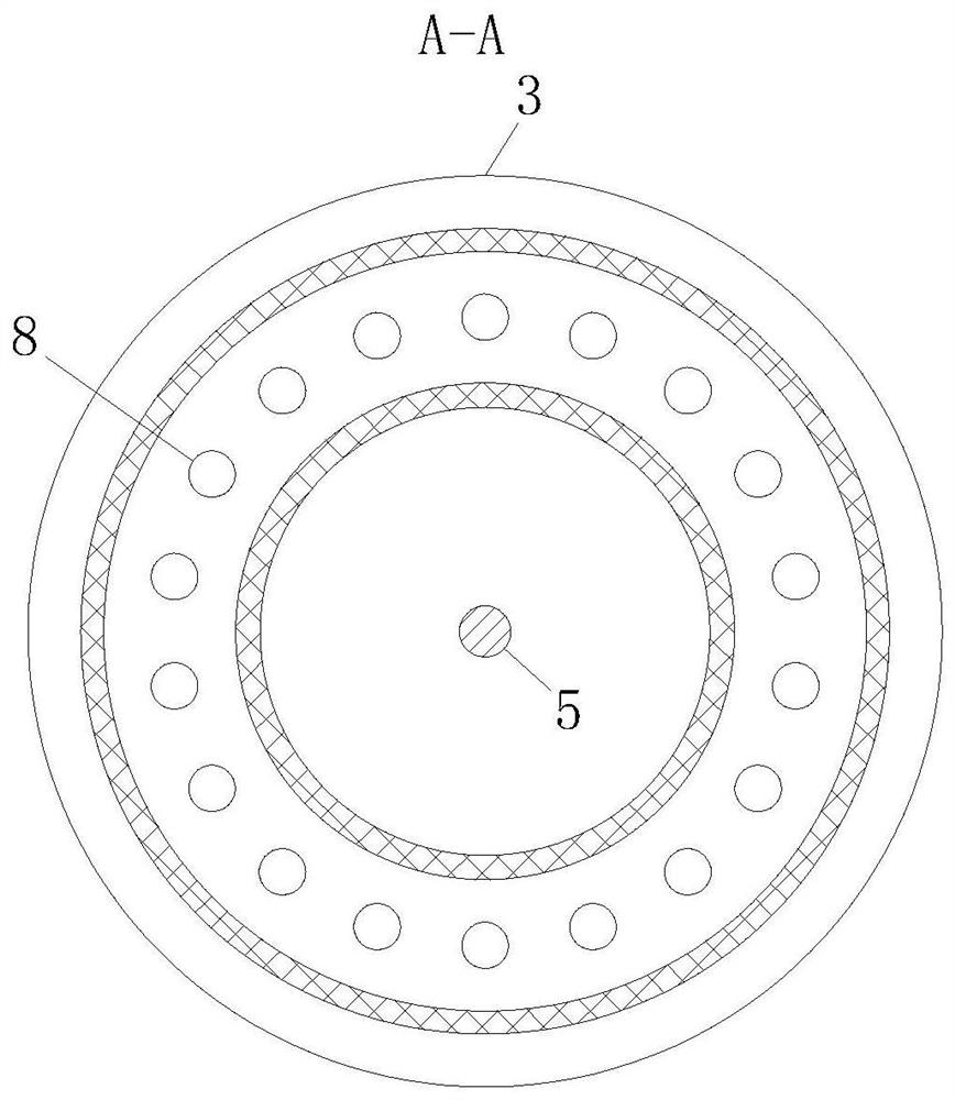
[0031] like Figure 1 to Figure 5 As shown, an ear massager for tinnitus rehabilitation treatment according to the present invention includes an arc-shaped connecting frame 1; power boxes 2 are installed at both ends of the arc-shaped connecting frame 1; An airbag 3 is fixedly connected to the side; a small motor 4 is installed in the power box 2; a rotating shaft 5 is fixedly connected to the output shaft of the small motor 4; a guide rod 6 is fixedly connected to the rotating shaft 5; 6. One end away from the rotating shaft 5 is fixedly connected with a tapered block 7; the circumference of the airbag 3 is evenly distributed with massage sticks 8, and the massage sticks 8 extend into the power box 2 and are slidably connected with it; the massage stick 8 and the airbag 3 are fixedly connected with an elastic rope 9; the small motor 4 drives the rotating shaft 5 to rotate, and then the guide rod 6 drives the conical block 7 to perform circular motion in the power box 2, so th...

Embodiment 2

[0040] like Figure 6 to Figure 7 As shown in Comparative Example 1, as another embodiment of the present invention, a buffer block 29 is affixed to the outside of the airbag 3 near the air outlet hole 16; a number of guide holes 30 are opened in the buffer block 29, and The guide holes 30 are scattered; through the setting of the buffer block 29, it is possible to prevent the airbag 3 from rebounding too much on the skin of the auricle, causing pain in the auricle of the user, and having a certain buffering effect. The four scattered guide holes 30 can make the air ejected from the pneumatic housing 12 disperse through each guide hole 30, thereby increasing the range of air blowing, providing a larger area of ​​ventilation and heat dissipation, and further promoting blood circulation.

[0041] The outlet end of the guide hole 30 is rotatably connected with a short shaft 31; the outer side of the short shaft 31 is fixed with a helical blade 32; the end of the short shaft 31 ex...


PUM


Abstract

The invention belongs to the technical field of medical devices, and specifically relates to an ear massager for tinnitus rehabilitation treatment, which includes an arc-shaped connecting frame; power boxes are installed at both ends of the arc-shaped connecting frame; Airbag; a small motor is installed in the power box; a rotating shaft is fixedly connected to the output shaft of the small motor; a tapered block is fixedly connected to the rotating shaft through a guide rod; massage sticks are evenly distributed on the circumference of the airbag, And the massage stick extends into the power box and is slidably connected with it; an elastic rope is fixedly connected between the massage stick and the air bag; The conical block regularly squeezes each massage stick, and then the massage stick slides towards the airbag one by one and squeezes the auricle through the airbag at this position, which improves the uniformity of the massage, so that each acupuncture point on the auricle can be massaged Massage can promote blood circulation, which is helpful for adjuvant treatment of tinnitus rehabilitation.

Description

technical field [0001] The invention belongs to the technical field of medical devices, in particular to an ear massager for tinnitus rehabilitation treatment. Background technique [0002] Tinnitus is a chronic disease that is very difficult to cure in the medical field. During the treatment, because of the various causes of tinnitus, doctors cannot guarantee a 100% cure during treatment, so ear massage is always used during the treatment of tinnitus adjuvant therapy. [0003] There are also some technical solutions for ear massagers in the prior art. For example, a Chinese patent with application number 2019100491631 discloses an ear massager for tinnitus rehabilitation, including a handle, external thread and a small motor. The outer side of the handle is wrapped with an outer protective sleeve, and the right side bolt of the handle is equipped with an end cover, the external thread is arranged on the outer left side of the handle, and a sterilization cover is arranged o...

Claims


Application Information

Patent Timeline
Patent Type & Authority Patents(China)
IPC IPC(8): A61F11/00A61H39/04A61H9/00A61H15/00
CPCA61F11/00A61F11/006A61H39/04A61H9/0078A61H15/00A61H2015/0064
Inventor 蔡跃新郑亿庆
Owner SUN YAT SEN MEMORIAL HOSPITAL SUN YAT SEN UNIV
Learn More