Stable soil improvement device
A soil improvement and stable technology, applied in the direction of soil lifting machinery, shovels, plows, etc., can solve the problems of the device moving left and right, the moving wheel can not move, difficult to control, etc., to prevent drug precipitation, easy to control, convenient effect of operation
- Summary
- Abstract
- Description
- Claims
- Application Information
AI Technical Summary
Problems solved by technology
Method used
Image

Examples
Embodiment 1
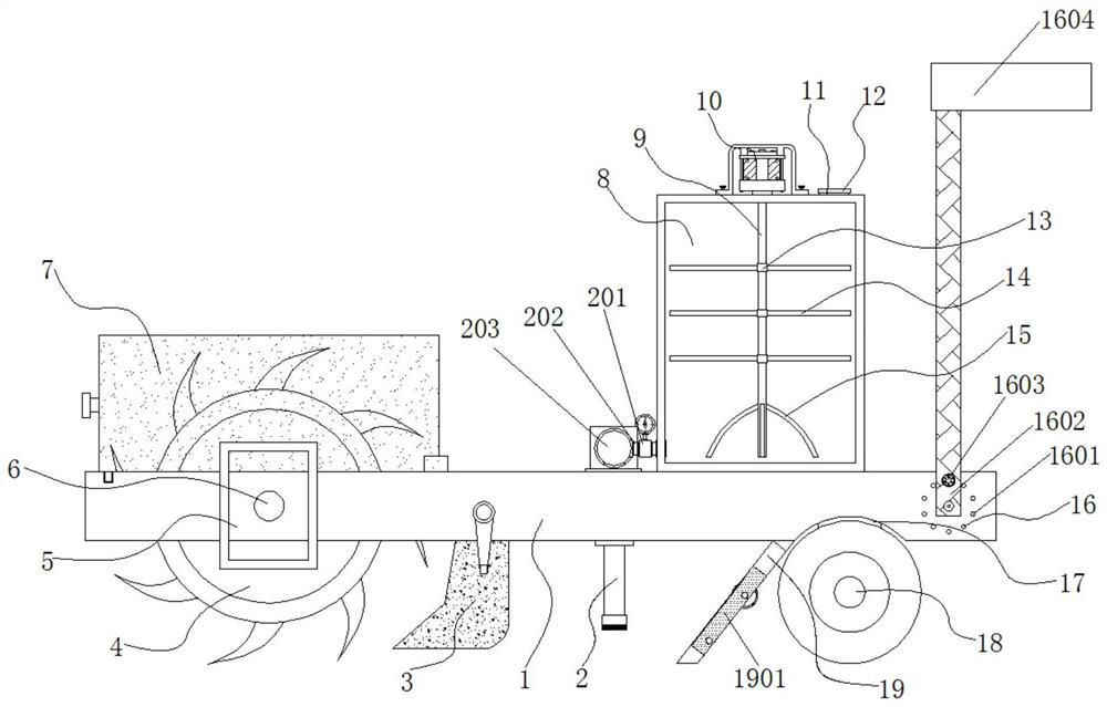
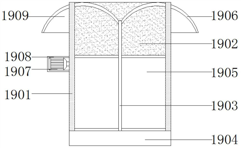
[0043] Embodiment 1: A stable soil improvement device, including a placement board 1, characterized in that: a side of the bottom end of the placement board 1 is provided with a leveling mechanism 19, and the leveling mechanism 19 includes a frame 1901, a connecting plate 1902, and a partition 1903 , shovel plate 1904, belt conveyor 1905, arc baffle plate 1906, third drive motor 1907, shell 1908 and sealing plate 1909;
[0044] A frame 1901 is fixedly connected to one side of the bottom end of the placement plate 1, a connecting plate 1902 is fixedly connected to the upper part of the frame 1901, and a belt conveyor 1905 is arranged on the lower part;
[0045] The middle end of connecting plate 1902 is fixedly connected with partition 1903, and partition 1903 is positioned at the front of belt conveyor 1905, and one side of belt conveyor 1905 is provided with the 3rd driving motor 1907, and the outer wall of the 3rd driving motor 1907 is fixedly sleeved with Shell 1908, the sh...
Embodiment 2
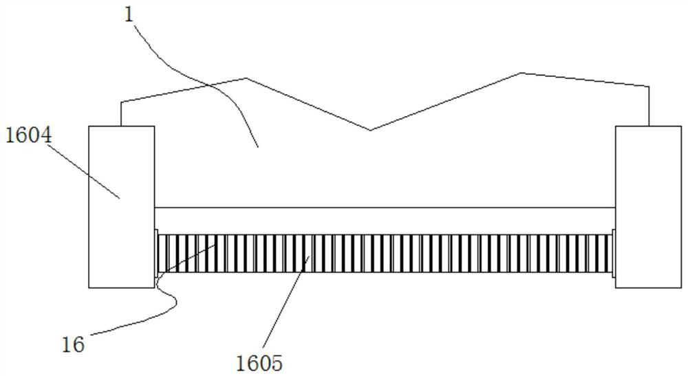
[0049] Example 2: see Figure 1-7 One side of the bottom end of the placing plate 1 is provided with an arc-shaped groove 17, the bottom end of the arc-shaped groove 17 is provided with a moving wheel 18, the bottom end of the placing plate 1 is provided with an auxiliary spraying structure 2, and one end of the placing plate 1 is provided with a second A drive motor 5, the model of the first drive motor 5 can be Y90L-2, the output end of the first drive motor 5 passes through the inside of one end of the placement plate 1 through the drive shaft and is fixedly connected with the shaft body 6, the outside of the shaft body 6 The turning roller 4 is fixedly connected, the top of the turning roller 4 is provided with a protective structure 7, the bottom end of the placing plate 1 on one side of the turning roller 4 is provided with an auxiliary collecting structure 3, and the side of the placing plate 1 is provided with an auxiliary adjusting structure 16. The top of the placeme...
Embodiment 3
[0053] Embodiment 3: Auxiliary spraying structure 2 is made up of valve 201, connecting pipe 202, water storage tank 203, water distribution pipe 204, movable sleeve 205, spray hole 206 and screen 207, one side of connecting pipe 202 and one side of mixing box 8 The bottom end of the connecting pipe 202 is fixedly connected, the outside of the connecting pipe 202 is provided with a valve 201, one side of the connecting pipe 202 is fixedly connected with a water storage tank 203, the bottom end of the water storage tank 203 is fixedly connected with a water distribution pipe 204, and the bottom end of the water distribution pipe 204 is provided with Spray hole 206, movable sleeve 205 is arranged on the outside of the bottom end of water distribution pipe 204, and the bottom end of movable sleeve 205 is fixedly connected with screen 207, and the bottom end of water distribution pipe 204 runs through the inside of placement plate 1 longitudinally, and connects one side of pipe 202 ...
PUM
 Abstract
Description
Claims
Application Information
 - Generate Ideas
- Intellectual Property
- Life Sciences
- Materials
- Tech Scout
- Unparalleled Data Quality
- Higher Quality Content
- 60% Fewer Hallucinations
Browse by: Latest US Patents, China's latest patents, Technical Efficacy Thesaurus, Application Domain, Technology Topic, Popular Technical Reports.
© 2025 PatSnap. All rights reserved.Legal|Privacy policy|Modern Slavery Act Transparency Statement|Sitemap|About US| Contact US: help@patsnap.com