
Composite circuit board with magnetoelectric composite interface

A magnetoelectric composite and composite circuit technology, applied in the direction of flexible printed circuit boards, printed circuits, printed circuit components, etc., can solve the problem of affecting the connection reliability of hard conductive electromagnetic particles, reducing the sensitivity or reliability of flexible electronic devices, Unable to meet the deformation requirements of flexible and extensible devices

Active Publication Date: 2021-09-28
INST OF FLEXIBLE ELECTRONICS TECH OF THU ZHEJIANG +1
View PDF6 Cites 0 Cited by
  • Summary
  • Abstract
  • Description
  • Claims
  • Application Information

AI Technical Summary

Problems solved by technology

[0003] However, when the surface of the object to which the flexible and extensible device is attached is uneven and has multiple electrodes, when the curvature or deformation of the surface of the flexible and extensible device is large, the surface of the attached object will stretch due to movement. Phenomena such as bending and folding seriously affect the connection reliability of hard conductive electromagnetic particles as a magnetoelectric composite interface
The magnetoelectric composite interface formed by conductive magnetic particles and its corresponding flexible circuit board still cannot meet the deformation requirements of flexible and stretchable devices, which leads to the risk of flexible and stretchable devices detaching from the magnetoelectric composite interface, which in turn leads to the sensitivity of flexible electronic devices Or the reliability is relatively reduced

Method used


Image

  • Composite circuit board with magnetoelectric composite interface
  • Composite circuit board with magnetoelectric composite interface

Examples


Embodiment Construction

[0025] In order to make the object, technical solution and advantages of the present invention clearer, the present invention will be further described in detail below in conjunction with the accompanying drawings and specific implementation methods. It should be understood that the specific embodiments described here are only used to explain the present invention, and do not limit the protection scope of the present invention.

[0026] It should be noted that when a component is said to be "mounted on" another component, it can be directly on the other component or there can also be an intervening component. When a component is said to be "set on" another component, it may be set directly on the other component or there may be an intervening component at the same time. When a component is said to be "fixed" to another component, it may be directly fixed to the other component or there may be an intervening component at the same time. The terms "vertical," "horizontal," "left...


PUM


Abstract

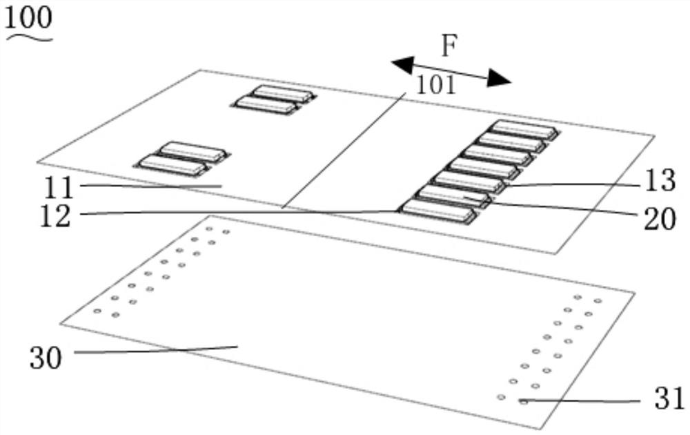
The invention relates to a composite circuit board with a magnetoelectric composite interface. The composite circuit board comprises a first flexible substrate and a conductive magnetic part; the first flexible substrate comprises a substrate body and an electrode connection region which are connected with each other, and an electrode is correspondingly arranged in the electrode connection region; the conductive magnetic part is fixed to the electrode connection region and electrically connected with the electrode, and the conductive magnetic part can serve as a magnetoelectric composite interface to be connected with an external device; the electrode connection region is provided with a hollow structure at the periphery of the area provided with the conductive magnetic part, so that the electrode connection region connected with the conductive magnetic part can be partially separated from the substrate body. According to the composite circuit board, the hollow structure is arranged on the first flexible substrate, so that the electrode connection region has a better degree of freedom in some directions, and the bending degree or the deformation degree corresponding to the electrode connection region is greatly improved.

Description

technical field [0001] The invention relates to the technical field of electronic devices, in particular to a composite circuit board with a magnetoelectric composite interface. Background technique [0002] With the rise of flexible smart terminals and wearable devices, medical, industrial and research fields are paying more and more attention to flexible, deformable and high-reliability circuit connection methods. The demand for flexible electronic devices with better bending is increasing day by day. Flexible electronic devices generally include flexible and extensible devices and corresponding flexible circuit boards (with control circuits that control the flexible and extensible devices). Flexible electronic devices use magnetoelectric composite interfaces to realize the detachable requirements between flexible and extensible devices (such as flexible sensors, etc.) and the main control circuit. At this time, traditional board-to-board, wire-to-wire and board-to-wire c...

Claims


Application Information

Patent Timeline
IPC IPC(8): H05K1/11
CPCH05K1/111H05K1/118H05K2201/05
Inventor 黄显汤明超杨晴
Owner INST OF FLEXIBLE ELECTRONICS TECH OF THU ZHEJIANG
Learn More