
Electronic equipment

A technology of electronic equipment and reinforcement, which is applied to branch equipment, circuits, antenna equipment with additional functions, etc., and can solve problems such as insufficient antenna placement, cracking of the whole machine, air tightness, and conflict.

Pending Publication Date: 2021-09-28
HUAWEI TECH CO LTD
View PDF0 Cites 0 Cited by
  • Summary
  • Abstract
  • Description
  • Claims
  • Application Information

AI Technical Summary

Problems solved by technology

At the same time, since 5G communication requires more antennas, the space on the top and bottom of the mobile phone is no longer enough to place all the antennas
Moreover, in the prior art, in order to meet the requirement of placing more antennas on the basis of placing more cameras, the antennas will be arranged on the antenna bracket, that is, on the molded plastic antenna bracket, laser technology is used to directly place the The metal antenna is formed by chemical plating on the antenna bracket, and this method requires a large area of ​​plastic space, which makes the antenna bracket occupy a large volume. When it is installed in the mobile phone, it is easy to cause conflicts with the motherboard space and increase the thickness of the mobile phone. , which is not conducive to the current thin and light design concept
On the premise of making the mobile phone thinner and thinner, more antenna layout requirements can be met, and the antenna will be excessively framed. In the scenario where it must be realized by adding side antenna slits, increasing the side slits will lead to the strength of the middle frame. Insufficient problems, causing reliability problems such as cracking of the whole machine and poor air tightness

Method used


Image

  • Electronic equipment
  • Electronic equipment
  • Electronic equipment

Examples


Embodiment Construction

[0042] Terms used in the embodiments of the present application are only for the purpose of describing specific embodiments, and are not intended to limit the present application. The singular forms "a", "said" and "the" used in the embodiments of this application and the appended claims are also intended to include plural forms unless the context clearly indicates otherwise.

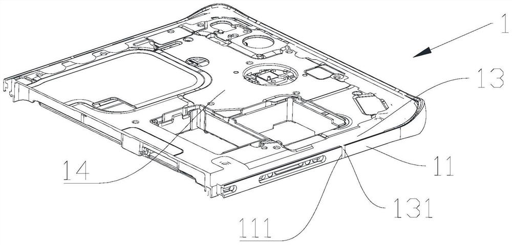
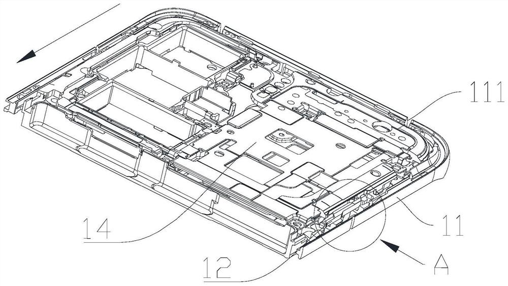
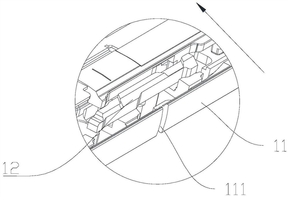
[0043] An embodiment of the present application provides an electronic device, such as figure 1 As shown, the electronic device has a middle frame assembly, and the middle frame assembly is used to install components such as a motherboard and a camera to form a corresponding electronic device, which is not specifically limited here. Taking the mobile phone as an example below, the middle frame assembly includes the middle frame 1, the middle frame 1 includes the middle part 14, the middle part 14 includes metal parts, and the middle part 14 is used to install electronic components. For the mobile phone ...


PUM


Abstract

The invention relates to the technical field of electronic products, in particular to electronic equipment. The electronic equipment comprises a middle frame, wherein the middle frame comprises a middle part, and the middle part comprises a metal piece; a center frame which is an insulating part; a side frame which comprises a metal piece, wherein the center frame is arranged between the middle part and the side frame, and the side frame is provided with at least one notch; a reinforcing part which is arranged in the middle frame, wherein the reinforcing part comprises a metal piece, the reinforcing part does not make contact with the metal piece of the side frame, the reinforcing part does not make contact with the metal piece of the middle part, and the projection of the reinforcing part on the plane where the side frame is located at least covers the notch. By utilizing the electronic equipment provided by the invention, more antenna layout requirements can be met, the performance of the antenna can be ensured, meanwhile, the structural strength of the corresponding position can be ensured, and the reliability of the whole machine can be ensured.

Description

technical field [0001] The present application relates to the technical field of electronic products, in particular to an electronic device. Background technique [0002] Traditional mobile phone antennas are generally located on the top and bottom of the mobile phone. In recent years, with the development of full-screen mobile phones and the increasing demand for hardware for taking pictures, more cameras need to be placed in the limited motherboard space, and the size of the camera Also getting bigger and bigger, the space available on the top and bottom of the antenna arrangement gradually decreases. At the same time, since 5G communication requires more antennas, the space on the top and bottom of the mobile phone is no longer enough to place all the antennas. Moreover, in the prior art, in order to meet the requirement of placing more antennas on the basis of placing more cameras, the antennas will be arranged on the antenna bracket, that is, on the molded plastic ante...

Claims


Application Information

Patent Timeline
Patent Type & Authority Applications(China)
IPC IPC(8): H01Q1/24H01Q1/44H04M1/02
CPCH01Q1/242H01Q1/44H04M1/026
Inventor 游玉霖张友良尤佳庆沈来伟谭小兵
Owner HUAWEI TECH CO LTD
Learn More