Circuit board inner layer punching machine die automatic position adjusting structure and position adjusting method

An automatic positioning and punching machine technology, applied in metal processing and other directions, can solve the problems of high labor intensity, scrapped circuit boards, and unsatisfactory accuracy, and achieve the goal of reducing labor intensity, reducing assembly processes, and improving work efficiency. Effect

Pending Publication Date: 2021-09-28
深圳市合精铭自动化机械设备有限公司
View PDF0 Cites 0 Cited by
  • Summary
  • Abstract
  • Description
  • Claims
  • Application Information

AI Technical Summary

Problems solved by technology

[0002] In the process of circuit board production, punching is a necessary process, and there are many automatic punching machines in the prior art, but the control accuracy is not satisfactory, and the punching needle is unstable during the punching process. And the problem of inaccurate alignment accuracy, and the replacement process of the punching needle is complicated and cumbersome, which not only wastes a lot of manpower, material resources and economic costs, but also easily leads to the scrapping of the circuit board
Moreover, in the prior art, manual visual positioning is mainly used before punching. The disadvantage of this positioning operation method is that it is labor-intensive, low in efficiency, and cannot meet the needs of unmanned operations.

Method used


Image

  • Circuit board inner layer punching machine die automatic position adjusting structure and position adjusting method
  • Circuit board inner layer punching machine die automatic position adjusting structure and position adjusting method
  • Circuit board inner layer punching machine die automatic position adjusting structure and position adjusting method

Examples


Embodiment 1

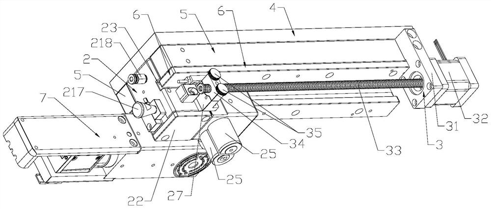
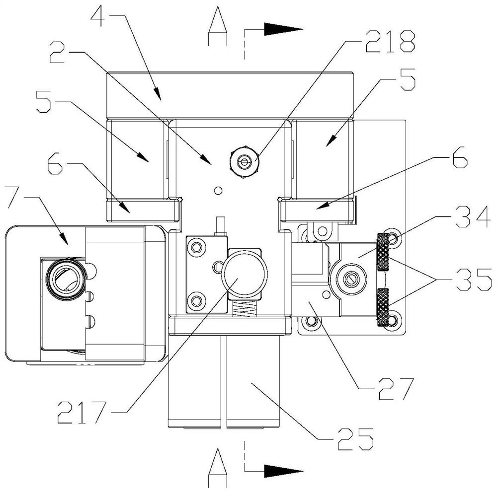
[0029] Please refer to Figure 1-4 , the present invention provides a circuit board inner layer punching machine mold automatic adjustment structure, which includes a mold 2 carrying an industrial camera 7 and at least one punching needle 1, and is used to drive the mold 2 to move to drive the punching needle 1. A displacement drive mechanism 3 that moves to a designated position, a positioning plate 4 with several positioning holes 41, and the positioning holes 41 are arranged along the moving path of the mold 2; wherein, the mold 2 also has a positioning assembly 21, The positioning assembly 21 includes a positioning pin 211 matched with the positioning hole 41 and an in-and-out driving mechanism for driving the positioning pin 211 into and out of the positioning hole 41 .

[0030] Specifically, the positioning assembly 21 also includes a sliding groove 212 and a return spring 213, the sliding groove 212 is arranged on one side of the mold 2, the positioning pin 211 is arran...

Embodiment 2

[0042] This embodiment also provides a method for automatically adjusting the mold of a circuit board inner layer punching machine realized by the adjusting structure of Embodiment 1, which includes the following steps: the in-out driving mechanism controls the positioning pin to escape from the positioning hole. At this time, there is an industrial camera The positioning plate with several positioning holes relative to the mold with at least one punching pin is in a free state, the displacement drive mechanism drives the mold to move to the designated position, and the in-out drive mechanism controls the positioning pin to enter the positioning hole at this position. At this time, the mold is relatively The positioning plate is in a fixed state to complete the adjustment of the mould.

[0043] Specifically, the process of the entry and exit drive mechanism controlling the movement of the positioning pin is as follows: after the air is inflated into the sealed cavity through th...


PUM


Abstract

The invention discloses a circuit board inner layer punching machine die automatic position adjusting structure and a position adjusting method. The position adjusting structure comprises a die, a movement driving mechanism and a positioning plate, wherein the die carries an industrial camera and at least one punching needle; the die is further provided with a positioning assembly; the movement driving mechanism is connected with the die and is used for driving the die to move so as to drive the punching needle to move; a plurality of positioning holes are formed in the positioning plate along the moving path of the die; and the positioning assembly comprises a positioning pin and an entry / exit driving mechanism for driving the positioning pin to go in or out of the positioning holes. According to the die automatic position adjusting structure, the punching needles are moved to the designated position through the movement driving mechanism, the die bearing the punching needles is further fixed to the designated position through cooperation of the positioning assembly and the positioning plate, and the situation that the punching precision is affected by dislocation caused by deviation when the punching needles move downwards is avoided; and the movement and positioning of the die are full-automatic processes without manual intervention, so that the labor intensity is greatly reduced, the working efficiency is improved, and the repeatability is good.

Description

technical field [0001] The invention relates to an automatic position adjustment structure and a position adjustment method for a mold of a circuit board inner layer punching machine. Background technique [0002] In the process of circuit board production, punching is a necessary process, and there are many automatic punching machines in the prior art, but the control accuracy is not satisfactory, and the punching needle is unstable during the punching process. And the problem of inaccurate alignment accuracy, and the replacement process of the punching needle is complicated and cumbersome, which not only wastes a lot of manpower, material resources and economic costs, but also easily causes scrapping of the circuit board. Moreover, in the prior art, manual visual positioning is mainly used before punching. The disadvantage of this positioning operation method is that it is labor-intensive, low in efficiency, and cannot meet the needs of unmanned operations. Contents of t...

Claims


Application Information

Patent Timeline
IPC IPC(8): B26F1/14B26F1/24B26D5/00B26D5/06B26D5/12B26D7/26B26D7/22B26D7/02
CPCB26F1/14B26F1/24B26D5/007B26D5/06B26D5/12B26D7/2614B26D7/2628B26D7/22B26D7/025B26F2210/08
Inventor 何精明
Owner 深圳市合精铭自动化机械设备有限公司
Why Eureka
Try Eureka