Special automatic welding machine for reinforcing ring web splicing

An automatic welding and reinforcing ring technology, applied in welding equipment, welding equipment, auxiliary welding equipment, etc., can solve the problems of high time cost and labor cost, offset between the center of the welding seam and the center of the copper pad, and low production efficiency. Achieve the effect of saving turning time, ensuring stability, and ensuring straightness

Pending Publication Date: 2021-09-28
大连中车大齐集装箱有限公司
View PDF6 Cites 0 Cited by
  • Summary
  • Abstract
  • Description
  • Claims
  • Application Information

AI Technical Summary

Problems solved by technology

Manual gas shielded welding double-sided welding requires high skill level of the welder, and the reinforcement ring needs to be turned 180° during the welding process, which is time-consuming and laborious, the production efficiency is low, and the welding quality is not easy to be guaranteed.
[0003] Welding trolley plus copper backing welding, although one-sided welding and double-sided molding can be realized, which saves the turning time, but every time a weld is completed, the track of the welding trolley needs to be moved and re-aligned. During the welding process, due to welding The reason for the deformation often leads to the offset problem between the center of the weld seam and the center of the copper pad,
[0004] In order to realize the welding of eight stitching welds, the time cost and labor cost required by the above two methods are also relatively high

Method used


Image

  • Special automatic welding machine for reinforcing ring web splicing
  • Special automatic welding machine for reinforcing ring web splicing
  • Special automatic welding machine for reinforcing ring web splicing

Examples


Embodiment 1

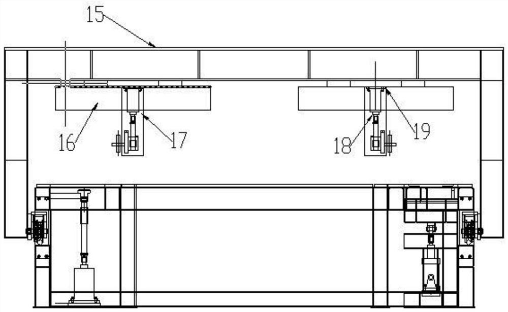
[0023] exist Figure 1 to Figure 6 In the schematic diagram of the present invention shown, the two vertical beams 1 lower ends of the gantry are respectively provided with traveling wheels 2, one of which is connected to the motor A3, and the traveling wheels can walk on the gantry base 4. A number of work support plates 5 are placed on the gantry base, and adjacent work support plates are provided with reserved copper liner installation grooves 6 at the splicing weld positions, and copper liner 7 is placed in the installation grooves. A positioning plate 8 is arranged on the work support plate. Four opening pressing mechanisms 9 are provided on the gantry base. The opening pressing mechanism includes a cylinder A, a fixed frame, a connecting rod, a rotating cylinder and an opening pressing piece. The cylinder A10 and the fixed frame 11 are arranged on the gantry base, the piston rod of the cylinder A is welded together with the connecting rod 12, the connecting rod passes ...


PUM


Abstract

The invention discloses a special automatic welding machine for reinforcing ring web splicing. According to the special automatic welding machine for reinforcing ring web splicing, walking wheels are arranged at the lower ends of two vertical beams of a portal frame correspondingly, one walking wheel is connected with a motor A, and the walking wheels can walk on a portal frame base; a plurality of working supporting plates are placed on the gantry frame base, reserved copper liner installation grooves are formed in the positions, at the splicing weld joints, of the adjacent working supporting plates, and copper liners are placed in the installation grooves; and a positioning plate is arranged on the working supporting plates. The walking gantry, a fixed rail and a transverse sliding table are matched, and longitudinal and transverse automatic welding is achieved; one-side welding and double-side forming of a splicing weld joint can be achieved through the copper liners of forming grooves, and meanwhile the time for overturning each time and the time for correcting a rail are saved; the reinforcing ring web can be conveniently positioned through the positioning plate conforming to the reinforcing ring web; and through an opening pressing mechanism, the stability of the reinforcing ring web in the welding process is guaranteed, and then the straightness of a web splicing welding seam and the copper liner is guaranteed.

Description

technical field [0001] The invention relates to the field of railway intermodal transportation, in particular to a special automatic welding machine. Background technique [0002] At present, internal I-shaped reinforcing rings are often used inside special-shaped tank containers, and the webs of I-shaped reinforcing rings need to be spliced ​​during the manufacturing process. The welding quality and welding speed of the spliced ​​weld ring seam are the main factors restricting this process , Usually the splicing welds are welded on both sides by manual gas shielded welding, or welded with a welding trolley and copper backing. Manual gas shielded welding double-sided welding requires high skill level of welders, and the reinforcement ring needs to be turned 180° during the welding process, which is time-consuming and laborious, with low production efficiency and difficult to guarantee welding quality. [0003] Welding trolley plus copper backing welding, although one-sided ...

Claims


Application Information

Patent Timeline
Patent Type & Authority Applications(China)
IPC IPC(8): B23K37/02B23K31/02B23K37/04
CPCB23K37/02B23K31/02B23K37/0443
Inventor 马天野杨启鹏沈正如丁乃余殷海斌杨宝双
Owner 大连中车大齐集装箱有限公司
Why Eureka
Try Eureka