
Patsnap Eureka
For R&D, Patsnap Eureka makes reading and utilizing patents & technical documents easy.
Patsnap Eureka AIR
Designed for self-driven R&D workflows. Generate viable solutions, solve complex R&D challenges, empower your innovation with AI.

Patsnap Eureka Materials
Designed for material experts only. Revolutionize your material R&D, from search, analyze, to developing new materials.

TechResearch
Generate reliable direction feasibility study reports for your R&D in just a few steps.

TechSeek
Discover and master advanced knowledge NOW. Basics, ideas, possibilities, all at once.

TechMind
As an expert in R&D Theories, TechMind can generates customized viable solutions instantly.

TechRisk
Analyze your overall solution with one click, know your potential R&D risks in advance.

TechMonitor
Get weekly tech updates, stay abreast of the latest tech innovations and key insights.
A kind of hull cleaning equipment for ocean engineering
A cleaning equipment and marine engineering technology, applied in the direction of hull, ship cleaning device, ship construction, etc., can solve the problems of polluting the environment, time and energy, and consumption, and achieve high efficiency, avoid marine pollution, and facilitate processing.
- Summary
- Abstract
- Description
- Claims
- Application Information
AI Technical Summary
Problems solved by technology
Method used
Image

Examples
Embodiment 1
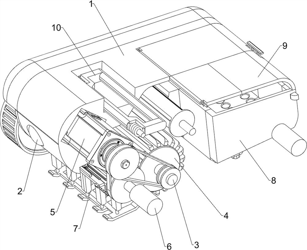
[0076] A kind of marine engineering hull cleaning equipment, such as figure 1 , figure 2 , image 3 , Figure 4 and Figure 5 As shown, it includes a casing 1, a lighting lamp 2, a first rotating rod 3, a cleaning roller 4, a power mechanism 5, and a moving mechanism 6. There is a first rotating rod 3, a cleaning roller 4 is arranged on the first rotating rod 3, a power mechanism 5 is arranged on the upper left side inside the casing 1, and a moving mechanism 6 is arranged on the lower part of the casing 1.
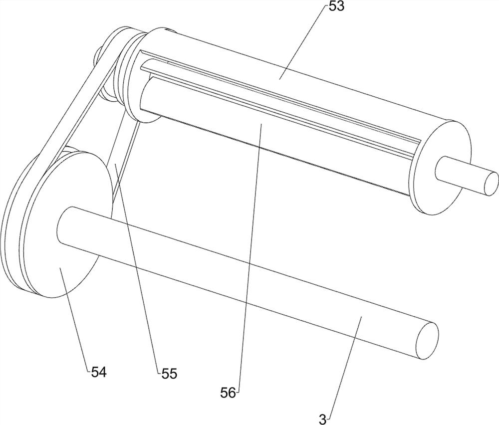
[0077] The power mechanism 5 includes a motor 50, a first transmission wheel 51, a first belt 52, a first support block 53, a second transmission wheel 54, a second belt 55 and a fan wheel 56, and the upper left side of the casing 1 is provided with a motor 50, The output shaft of the motor 50 and the front side of the first rotating rod 3 are provided with a first transmission wheel 51, and a first belt 52 is wound between the first transmission wheels 51. The upper...
Embodiment 2
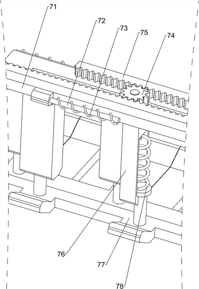
[0081] On the basis of Example 1, such as figure 2 , Figure 6 and Figure 7 As shown, scraping assembly 7 is also included, and scraping assembly 7 includes rotating disk 70, first connecting rod 71, first guide rod 72, first spring 73, gear 74, rack 75, third support block 76, A scraper 77 and a second spring 78, a turntable 70 is provided on the rear side of the second rotating rod 60 on the left side, four first guide rods 72 are provided on the left middle part inside the housing 1, and two first guide rods 72 on the same side The first connecting rod 71 is slidingly arranged between them, the first connecting rod 71 on the left side cooperates with the turntable 70, the first spring 73 is wound on the first guide rod 72, and the two ends of the first spring 73 are connected with the first connecting rod respectively. The connecting rod 71 is connected with the shell 1, and the left middle part of the inside of the shell 1 is rotatably provided with a gear 74, the gear...
Embodiment 3
[0084] On the basis of Example 2, such as figure 1 , figure 2 , Figure 8 , Figure 9 , Figure 10 , Figure 11 and Figure 12 As shown, it also includes a collection assembly 8, and the collection assembly 8 includes a second guide rod 80, a guide slider 81, a third spring 82, a collection frame 83, a limit block 84, a third guide rod 85, a first wedge block 86 and the fourth spring 87, the inner lower right side of the housing 1 is symmetrically provided with a second guide rod 80, the left side of the second guide rod 80 is slidably provided with a guide slider 81, and the left side of the second guide rod 80 is wound with a The third spring 82, the two ends of the third spring 82 are respectively connected with the guide slider 81 and the housing 1, the left side of the second guide rod 80 is slidingly provided with a limit block 84, and the limit block 84 is located on the right side of the guide slider 81, A collection frame 83 is arranged between the insides of t...
PUM
 Abstract
Description
Claims
Application Information
 - R&D Engineer
- R&D Manager
- IP Professional
- Industry Leading Data Capabilities
- Powerful AI technology
- Patent DNA Extraction
Browse by: Latest US Patents, China's latest patents, Technical Efficacy Thesaurus, Application Domain, Technology Topic, Popular Technical Reports.
© 2024 PatSnap. All rights reserved.Legal|Privacy policy|Modern Slavery Act Transparency Statement|Sitemap|About US| Contact US: help@patsnap.com