Switching device

A transfer device and interface technology, which is applied to the components of the connection device, coupling device, and measurement device, can solve problems affecting test results, etc., and achieve the effects of simplifying the wiring structure, improving test efficiency, and simplifying the test environment

Active Publication Date: 2021-09-21
SPREADTRUM COMM (SHANGHAI) CO LTD
View PDF4 Cites 0 Cited by
  • Summary
  • Abstract
  • Description
  • Claims
  • Application Information

AI Technical Summary

Problems solved by technology

[0003]The purpose of the present invention is to provide a transfer device, which is used to solve the problem in the prior art that the test results are affected by the reserved wiring channels on the test device

Method used


Image

  • Switching device
  • Switching device
  • Switching device

Examples


Embodiment 1

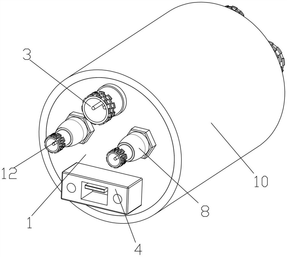
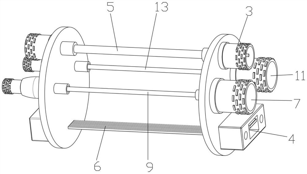
[0074] Aiming at the problems existing in the prior art, Embodiment 1 of the present invention provides a switching device, such as Figure 1 to Figure 3 As shown, it includes: a first fixed plate 1, a second fixed plate 2, two power cord interfaces 3, two USB (Universal Serial Bus, Universal Serial Bus) interfaces 4, a first connecting line 5, a second connecting line 6. The first radio frequency male connector 7, the first radio frequency female connector 8, the first radio frequency connection line 9 and the outer cover 10, the outer cover 10 is hollow, and the first fixing plate 1 and the second fixing plate 2 are respectively arranged at both ends of the outer cover 10 , and the outer cover 10, the first fixed plate 1 and the second fixed plate 2 form a closed space, and the two power cord interfaces 3 are respectively arranged on the first fixed plate 1 and the second fixed plate 2, and the two ends of the first connecting line 5 They are respectively electrically connec...

Embodiment 2

[0085] Embodiment 2 is an improved solution of Embodiment 1, and its improvements are as follows: Figure 4 to Figure 10 As shown, it also includes: wire transfer device 14, docking device 17, at least one third radio frequency connection line 16 and at least two groups of sliding assemblies 15, the number of sliding assemblies 15 is the same as that of the first radio frequency connection line 9 and the third radio frequency connection line 16 The sum of the numbers is equal, the first radio frequency connection line 9 and the third radio frequency connection line 16 are respectively arranged on a group of sliding assemblies 15, the wire transfer device 14 and the docking device 17 are all arranged in a closed space, and each sliding assembly 15 is provided with On the wire transfer device 14, the wire transfer device 14 is used to adjust the position of the sliding assembly 15, and the docking device 17 is used to drive the first radio frequency connection line 9 or the third...


PUM


Abstract

The invention provides a switching device which comprises a first fixing plate, a second fixing plate, two power line interfaces, two USB interfaces, a first connecting line, a second connecting line, a first radio frequency male head, a first radio frequency female head, a first radio frequency connecting line and an outer cover, wherein the outer cover is hollow, and the first fixing plate and the second fixing plate are arranged at the two ends of the outer cover respectively; the two power line interfaces and the two USB interfaces are respectively arranged on the first fixing plate and the second fixing plate, the first connecting line is connected with the two power line interfaces, the second connecting line is connected with the two USB interfaces, the first radio frequency male head is arranged on the first fixing plate, the first radio frequency female head is arranged on the second fixing plate, and the first radio frequency connecting line is connected with the first radio frequency male head and the first radio frequency female head. The switching device is used for solving the problem that in the prior art, a wiring channel is reserved on a testing device, so that the testing result is affected, the wiring structure can be simplified, and the wiring complexity of a connecting line of a tested product is reduced.

Description

technical field [0001] The invention relates to the field of detection interfaces, in particular to a switching device. Background technique [0002] With the development of science and technology, intelligent devices are constantly integrated into people's daily life, such as mobile phones, tablets, etc., have gradually become very important tools in people's lives. In order to further improve the application scenarios of smart devices such as mobile phones, it is necessary to test the prototype in extreme environments (-40 to +85°C), and collect operating information such as the standby time and performance usage of the prototype in different temperature environments. In the current test method, it is usually necessary to reserve a wiring channel on the test device, which is likely to affect the test result and reduce the accuracy of the test. Contents of the invention [0003] The purpose of the present invention is to provide an adapter device for solving the problem ...

Claims


Application Information

Patent Timeline
IPC IPC(8): H01R31/06H01R27/00H01R13/502H01R13/533G01R1/04
CPCH01R31/06H01R27/00H01R13/502H01R13/533G01R1/0416
Inventor 李祖明解芃许秀娟张浩鹏袁露露
Owner SPREADTRUM COMM (SHANGHAI) CO LTD
Why Eureka
Try Eureka