Mobile phone display screen pressure resistance testing device and using method thereof
A technology of withstand voltage test and test device, applied in the direction of measuring device, using stable tension/pressure test material strength, instrument, etc., can solve the test of mobile phone screen damage, single test method, inconvenient high precision, high compatibility test And other issues
- Summary
- Abstract
- Description
- Claims
- Application Information
AI Technical Summary
Problems solved by technology
Method used
Image
Examples
Embodiment 1
[0043] see figure 1 and figure 2 , a mobile phone display screen voltage withstand test device in the figure, including a main frame 1 and a controller 2, the main frame 1 is mounted with a controller 2 on the surface, and the top of the main frame 1 is installed with a high-precision pressure Pressing device 4, the bottom of the pressing device 4 is equipped with a test device 5 that can convert the station, and four test rods 6 are evenly installed on the outside of the test device 5, and the controller 2 is respectively connected with the bearing device 3 and the bottom The pressure device 4 is electrically connected.
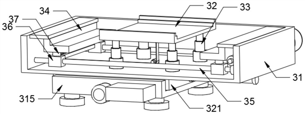
[0044] see image 3 , Figure 4 and Figure 5 , the carrying device 3 includes a carrying frame 31, a carrying plate 32, an elastic telescopic column 33, a corner plate 34, a two-way screw 35, a moving block 36, a pressure sensor 37, a first motor 38, a transmission rod 39, a worm 310, a worm wheel 311, connecting rope 312, guide wheel 313 and cross ba...
Embodiment 2
[0057] see Figure 13 and Figure 14 , the test device 5 includes a main plate B59, an empty slot B510, a shaft column B511, a cross plate 512, a telescopic frame 513 and a tension spring 514, the main plate B59 is provided with an empty slot B510 inside, and one side of the main plate B59 is A shaft column B511 is rotatably installed, and a telescopic frame 513 is slidably inserted on the other side of the main disk B59. A cross plate 512 is arranged inside the empty slot B510, and the cross plate 512 is fixedly connected to the telescopic frame 513. The cross plate 512 The telescopic frame 513 is elastically connected to the main plate B59 through the tension spring 514 in cooperation with the shaft column B511.
[0058] When changing the station of the test rod 6, the telescopic frame 513 is pulled outward against the elastic force of the tension spring 514, so that the cross plate 512 is withdrawn from the clamping connection with the shaft column B511, and the main plate...
Embodiment 3
[0060] see Figure 15, the test device 5 includes a main plate C515, an empty groove C516, an embedded groove 517, an embedded handle 518, a shaft column C519, a positioning column 520, a positioning hole 521, a reset groove 522, a wire rope 523 and a runner 524. The main plate A shaft column C519 is rotatably installed on one side of the C515, and an insert groove 517 is formed on the other side of the main plate C515. The insert groove 517 is slidably installed with an insert handle 518. The main plate C515 has an empty groove C516 inside. A positioning hole 521 corresponding to the position of the test rod 6 is opened on the surface of the shaft column C519, a reset groove 522 is symmetrically opened inside the main disk C515, and a positioning column 520 is elastically installed in the reset groove 522 through a spring, and the positioning column 520 is connected with the positioning The holes 521 are structurally matched, a runner 524 is installed inside the cavity C516 ,...
PUM
 Abstract
Description
Claims
Application Information
 - R&D
- Intellectual Property
- Life Sciences
- Materials
- Tech Scout
- Unparalleled Data Quality
- Higher Quality Content
- 60% Fewer Hallucinations
Browse by: Latest US Patents, China's latest patents, Technical Efficacy Thesaurus, Application Domain, Technology Topic, Popular Technical Reports.
© 2025 PatSnap. All rights reserved.Legal|Privacy policy|Modern Slavery Act Transparency Statement|Sitemap|About US| Contact US: help@patsnap.com


