Tubular beam connecting joint

A tube beam and end tube technology, which is applied in the connection of rods, connecting components, mechanical equipment, etc., can solve the problems of time-consuming and laborious, low connection precision between tube beams and ordinary joints, and inability to disassemble and reassemble.

Pending Publication Date: 2021-09-14
清华大学苏州汽车研究院(吴江) +1
View PDF0 Cites 0 Cited by
  • Summary
  • Abstract
  • Description
  • Claims
  • Application Information

AI Technical Summary

Problems solved by technology

[0002] The pipe beam has a simple structure and reliable strength. It is one of the commonly used materials in automobile manufacturing. During the manufacturing process of the car body structure, multiple pipe beams need to be connected. At present, the connection of multiple pipe beams is mostly welded or ordinary joints After the connection, the screws are fixed. However, multiple pipe beams cannot be disassembled and reassembled after being fixedly connected by welding, and it is time-consuming and laborious. After connecting multiple pipe beams through ordinary 2-way, 3-way or 4-way joints, use Screws are used to connect the pipe beams and common joints to fix them. In this way, the connection precision and strength of the pipe beams and common joints are low, and the assembly requires tooling and fixtures for positioning, which is inefficient.

Method used


Image

  • Tubular beam connecting joint
  • Tubular beam connecting joint
  • Tubular beam connecting joint

Examples


Embodiment Construction

[0027] The present invention is further detailed in conjunction with the accompanying drawings and examples. It will be appreciated that the specific embodiments described herein are merely illustrative of the invention and are not limited thereto. It will also be noted that in order to facilitate the description, only the parts associated with the present invention are shown in the drawings rather than all structures.

[0028] In the description of the present invention, the term "connected", "connection", "fixed", unless otherwise expressly specified and defined, and "fixed", for example, may be a fixed connection, or a detachable connection, or integral However, it can be a mechanical connection, or may be electrically connected; may be directly connected, or can be indirectly connected by an intermediate medium, which may be a communication between two elements or two components. Relationship. The specific meaning of the above terms in the present invention will be appreciated...


PUM


Abstract

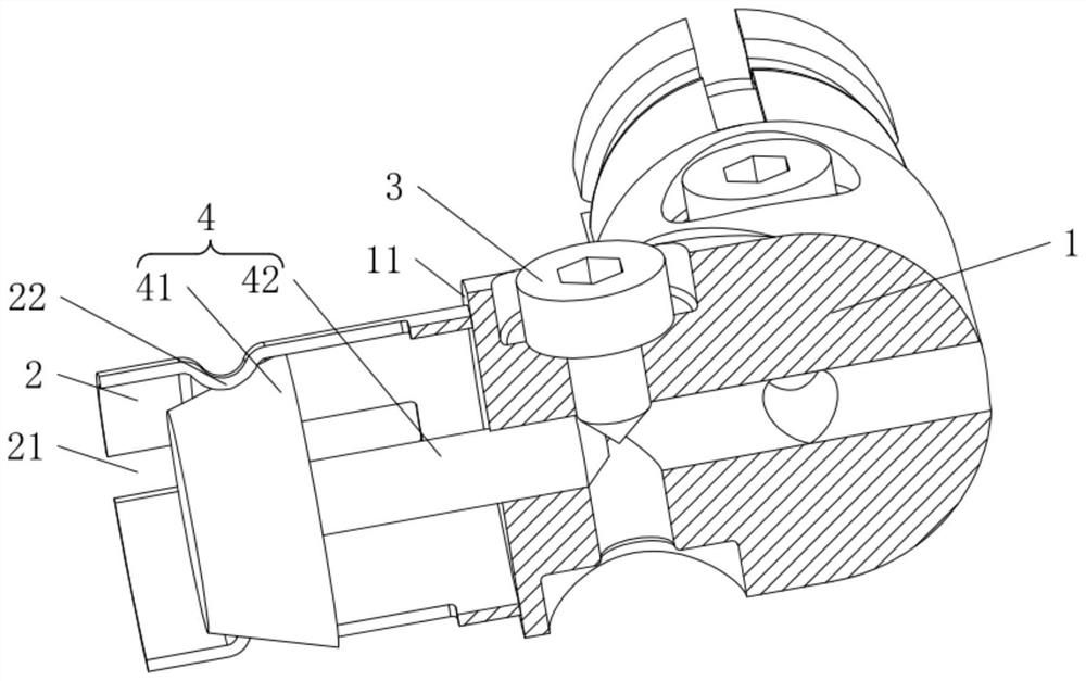
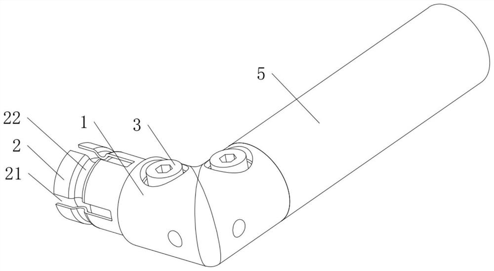
The invention belongs to the technical field of tubular beam joints, and discloses a tubular beam connecting joint. The tubular beam connecting joint comprises a plurality of joints, each joint comprises a base, an end pipe, a screw and an ejecting core, the end pipes are fixedly connected with the bases, the bases are provided with threaded holes, the screws are in threaded connection with the threaded holes, the end pipes are provided with a plurality of openings, and the openings are arranged at intervals in the circumferential direction of the end pipes. The ejecting cores are arranged in the end pipes and the bases in a sliding manner, the end pipes are provided with protrusions, the ejecting cores abut against the protrusions, the screws are configured to push the ejecting cores to slide and extrude the protrusions so as to expand the end pipes, and the multiple bases are fixedly connected. The tubular beam connecting joint can be conveniently and quickly mounted and dismounted with a tubular beam, and is high in matching precision and strength with the tubular beam.

Description

Technical field [0001] The present invention relates to a pipe joint beam technology, and particularly relates to a tubular beam coupling joint. Background technique [0002] Tubular beam strength simple structure and reliable, is commonly used in automobile manufacturing material, the body structure in the manufacturing process, it is necessary to perform a plurality of tubular beams coupled, at present, a plurality of tubes connected to a multi-beam welding or by conventional linker after the connection screws, but by welding after fixing the tubes connecting the plurality of beams can not be removed and re-assembled, and time-consuming; by a general 2-way, 3-way or 4-way joint after connecting a plurality of tubular beam, and then taking over ordinary beam and screw tightening joint to secure, in this way the accuracy of the beam pipe connection joint and the general low, low strength, and the fixture needs to be positioned during assembly, inefficient. Inventive content [0...

Claims


Application Information

Patent Timeline
Patent Type & Authority Applications(China)
IPC IPC(8): F16B7/04
CPCF16B7/0466F16B7/0446
Inventor 迟达余丽娟
Owner 清华大学苏州汽车研究院(吴江)
Why Eureka
Try Eureka