
Direct-current permanent magnet type self-absorption composite shield pump with gas-liquid mixing cavity

A gas-liquid mixing and composite shielding technology, applied in non-variable volume pumps, components of pumping devices for elastic fluids, pumps, etc., can solve problems such as self-priming or weak suction, limited energy efficiency, etc.

Active Publication Date: 2021-09-14
陈荣国
View PDF5 Cites 1 Cited by
  • Summary
  • Abstract
  • Description
  • Claims
  • Application Information

AI Technical Summary

Problems solved by technology

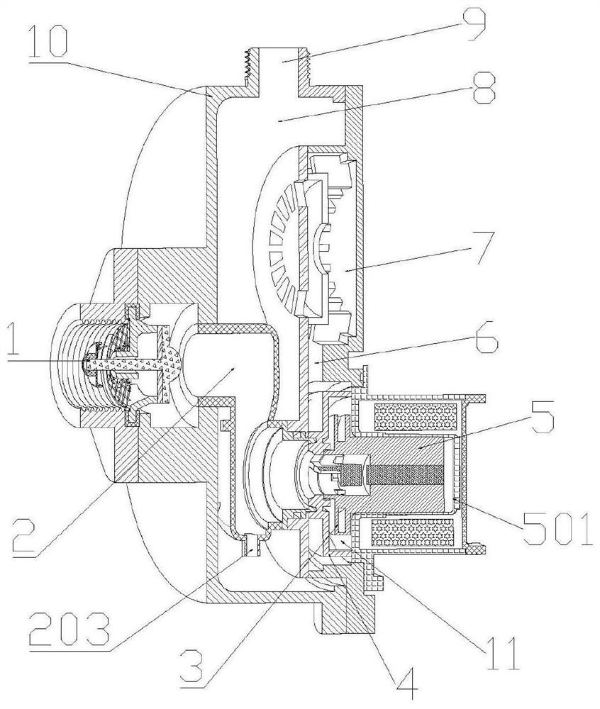
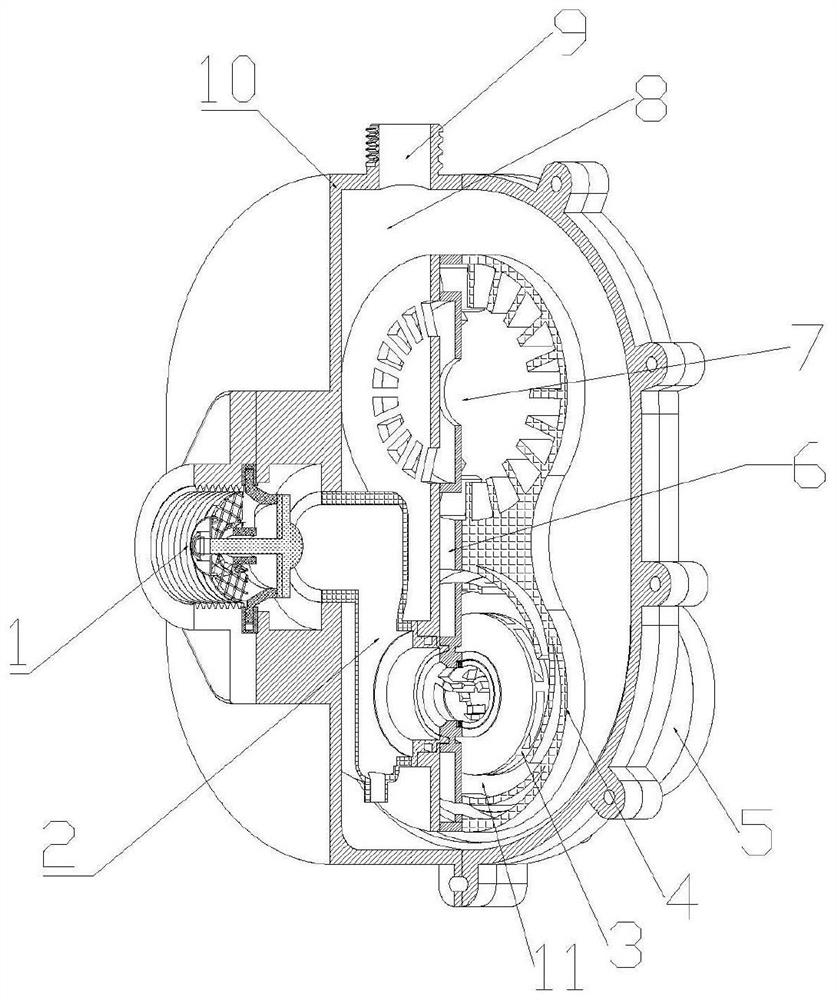
[0004] In view of the problems that most of the existing canned pumps do not have self-priming or have weak suction and limited energy efficiency, the purpose of the present invention is to provide a pump with self-priming, outstanding performance in flow rate, head, suction, etc., strong safety, and compact structure. DC permanent magnet self-priming compound canned pump

Method used


Image

  • Direct-current permanent magnet type self-absorption composite shield pump with gas-liquid mixing cavity
  • Direct-current permanent magnet type self-absorption composite shield pump with gas-liquid mixing cavity
  • Direct-current permanent magnet type self-absorption composite shield pump with gas-liquid mixing cavity

Examples


Embodiment Construction

[0049]In order to enable those skilled in the art to better understand the technical solution in the present invention, the technical solution in the invention will be clearly and completely described below in conjunction with the accompanying drawings in the present invention, and what is obviously described is only a part of the present invention Examples, not all examples. Based on the embodiments of the invention, all other embodiments obtained by persons of ordinary skill in the art without creative efforts shall fall within the protection scope of the invention.

[0050] In this regard, the present invention uses a DC permanent magnet motor to reduce the overall size of the pump body by greatly reducing the centrifugal impeller and increasing the motor speed, while ensuring that the overall performance of the pump meets the needs of practical applications. The reasonable configuration of the gas-liquid mixing chamber and the buffer booster chamber realizes the self-primi...


PUM


Abstract

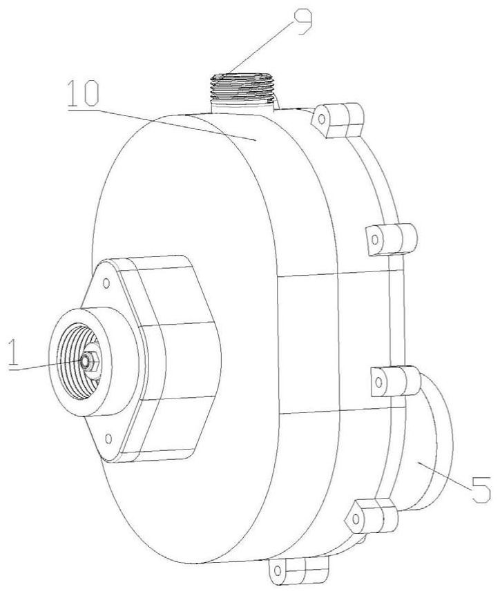
The invention discloses a direct-current permanent magnet type self-absorption composite shield pump with a gas-liquid mixing cavity. The direct-current permanent magnet type self-absorption composite shield pump comprises a pump inlet, a gas-liquid mixing cavity, a centrifugal end, a buffer booster cavity, a gas-liquid separation chamber and a pump outlet, wherein the pump inlet is connected with an inlet of the gas-liquid mixing cavity, an outlet of the gas-liquid mixing cavity is connected with an inlet of the centrifugal end, an outlet of the centrifugal end is communicated with an inlet of the buffer booster cavity, an outlet of the buffer booster cavity is communicated with the gas-liquid separation chamber, and the gas-liquid separation chamber is communicated with the pump outlet; the buffer booster cavity is used for rapidly reducing the speed of high-speed pressure fluid at the outlet of the centrifugal end and boosting the high-speed pressure fluid; in the exhaust self-suction stage, the flow speed of gas-liquid mixed fluid is reduced, and meanwhile bubble breakage is reduced; and in the non-exhaust stage, flow resistance is reduced, pressure loss is reduced, and meanwhile buffer boosting of the fluid at the outlet of the centrifugal end is achieved. A direct-current permanent magnet motor is combined with the gas-liquid mixing cavity and the shield pump, so that the shield pump has the characteristics of strong self-absorption and good hydraulic characteristic, the spatial position and the internal structure of the buffer booster cavity are ingeniously arranged, and the technical problem that gas-liquid separation is difficult due to the fact that bubbles in the composite shield pump are seriously broken at a high rotating speed is effectively solved.

Description

technical field [0001] The invention relates to a self-priming compound canned pump, in particular to a DC permanent magnet self-priming compound canned pump with a gas-liquid mixing chamber, which belongs to the field of fluid machinery. Background technique [0002] As we all know, the canned pump is a fully static sealed structure, no risk of leakage, high reliability pump, its volume can be very small, and has the advantage of super quiet, widely used in many fields such as chemical industry, civil water supply and drainage, household appliances, etc. , especially in the transportation of precious, flammable, explosive, radioactive and corrosive fluid media, which play a key technical support role. Recently, there is a huge demand for wall-hung boilers and water heaters. The output value of these two fields in China is not fully counted. Has exceeded 2 billion. The canned pump has a unique structure, which can seal the motor and the pump body in a certain canned pump pu...

Claims


Application Information

Patent Timeline
IPC IPC(8): F04D13/06F04D9/06F04D29/42
CPCF04D13/0606F04D9/06F04D29/426
Inventor 陈荣国
Owner 陈荣国
Learn More