
Adjustable supporting seat for photovoltaic equipment and use method of adjustable supporting seat

A technology of photovoltaic equipment and support seat, which is applied to the support structure of photovoltaic modules, photovoltaic power generation, photovoltaic modules, etc., and can solve the lack of wind resistance, wind resistance performance not meeting the requirements, irreparable damage of photovoltaic panels and photovoltaic supports And other issues

Inactive Publication Date: 2021-09-10
张正勇
View PDF0 Cites 0 Cited by
  • Summary
  • Abstract
  • Description
  • Claims
  • Application Information

AI Technical Summary

Problems solved by technology

Especially in areas with strong winds, if the wind resistance of photovoltaic panels and photovoltaic supports is lacking, it is very easy to cause irreparable damage to photovoltaic panels and photovoltaic supports
In the traditional way, the above problems are mainly solved by increasing the structural strength of the photovoltaic support and increasing its support rigidity so that it can resist strong winds. However, the wind resistance effect achieved by this method is limited, and it is more suitable for areas with low wind levels. , but for areas with higher wind levels, the wind resistance performance cannot meet the requirements

Method used


Image

  • Adjustable supporting seat for photovoltaic equipment and use method of adjustable supporting seat
  • Adjustable supporting seat for photovoltaic equipment and use method of adjustable supporting seat
  • Adjustable supporting seat for photovoltaic equipment and use method of adjustable supporting seat

Examples


Embodiment Construction

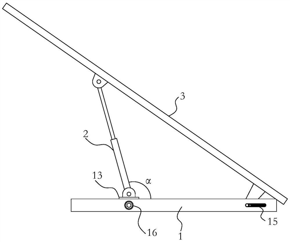
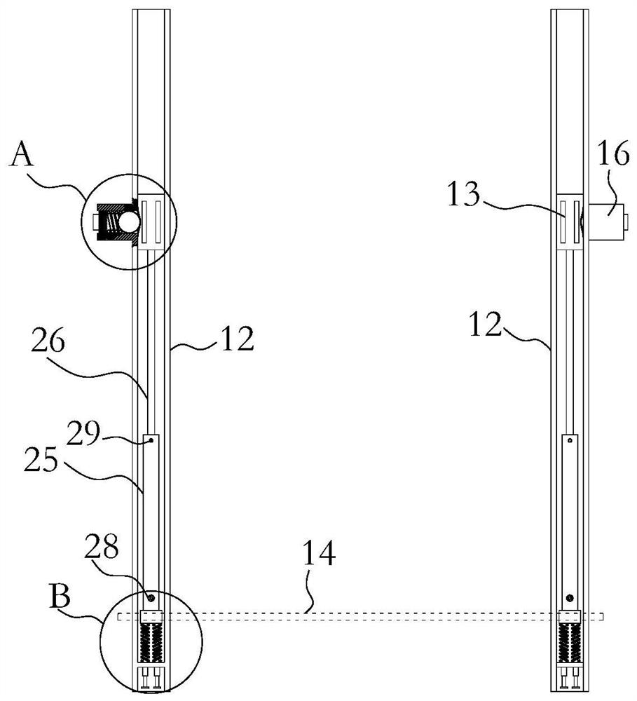
[0027] Such as Figure 1-9 The photovoltaic support shown includes a base frame 1 , a telescopic adjustment rod 2 and a fixing frame 3 for installing a photovoltaic panel 0 . The underframe 1 is installed on the ground as an installation basis, and it can be installed on the ground in various ways such as placement and anchoring, and can be selected from existing installation methods according to actual conditions. The lower end of the fixed frame 3 is hinged with the bottom frame 1, the middle part of the fixed frame 3 is hinged with the upper end of the telescopic adjustment rod 2, the lower end of the telescopic adjustment rod 2 is hinged with the bottom frame 1, and forms an obtuse angle α with the bottom frame 1 . By adjusting the length of the telescopic adjusting rod 2, the angle of the fixing frame 3 is changed, thereby changing the angle of the photovoltaic panel 0 installed thereon.

[0028] Compared with the traditional photovoltaic support, this invention mainly ...


PUM


Abstract

The invention relates to the field of the photovoltaic technology. The invention aims to provide an adjustable supporting seat for photovoltaic equipment. The adjustable supporting seat comprises a bottom frame, a telescopic adjusting rod and a fixing frame for mounting a photovoltaic panel. The bottom frame comprises two U-shaped grooves which are arranged side by side, supporting seats are arranged at the positions, opposite to the lower ends of the telescopic adjusting rods, of the U-shaped grooves, the lower ends of the telescopic adjusting rods are hinged to hinge lugs at the tops of the supporting seats, the supporting seats are in sliding fit with the U-shaped grooves, and first pressure limiting locking assemblies are arranged at the positions, opposite to the supporting seats, of the U-shaped grooves. A transverse shaft is arranged at the lower end of the fixing frame, adjusting holes matched with the transverse shaft are formed in the groove walls of the two sides of the U-shaped groove, the adjusting holes extend in the length direction of the U-shaped grooves, the transverse shaft is arranged in the adjusting holes in a penetrating mode, and a second pressure limiting locking assembly connected with the transverse shaft is arranged in the position, at the adjusting holes, of the U-shaped grooves. The adjustable supporting seat can be automatically folded when affected by disastrous strong wind, and the photovoltaic panel is prevented from being damaged.

Description

technical field [0001] The invention relates to the field of photovoltaic technology, in particular to an adjustable support base for photovoltaic equipment and a method for using the same. Background technique [0002] Photovoltaic power generation is a technology that directly converts light energy into electrical energy by using the photovoltaic effect of the semiconductor interface. In recent years, as the world's energy supply contradictions have intensified, photovoltaics have received more and more attention as a sustainable clean energy. Its position in the energy supply system is also becoming more and more important. Generally speaking, the photovoltaic system mainly includes photovoltaic panels, combiner boxes, inverters, and grid-connected cabinets. Complete the merger with the grid. Photovoltaic panels generally need to be installed on photovoltaic supports for use, and because photovoltaic panels need to be installed outdoors, this also puts forward extremely...

Claims


Application Information

Patent Timeline
IPC IPC(8): H02S20/30
CPCH02S20/30Y02E10/50
Inventor 张正勇
Owner 张正勇
Learn More