Clutch device for power tool

A technology for clutch devices and electric tools, which is applied in the field of clutch devices, can solve problems such as reliability needs to be improved, and achieve the effect of improving safety and reliability

Active Publication Date: 2015-08-19
ZHEJIANG TONGDA ELECTRICAL APPLIANCE
View PDF5 Cites 0 Cited by
  • Summary
  • Abstract
  • Description
  • Claims
  • Application Information

AI Technical Summary

Problems solved by technology

The safety and reliability of the clutch device used on the electric hammer in the prior art needs to be improved

Method used


Image

  • Clutch device for power tool
  • Clutch device for power tool
  • Clutch device for power tool

Examples


Embodiment Construction

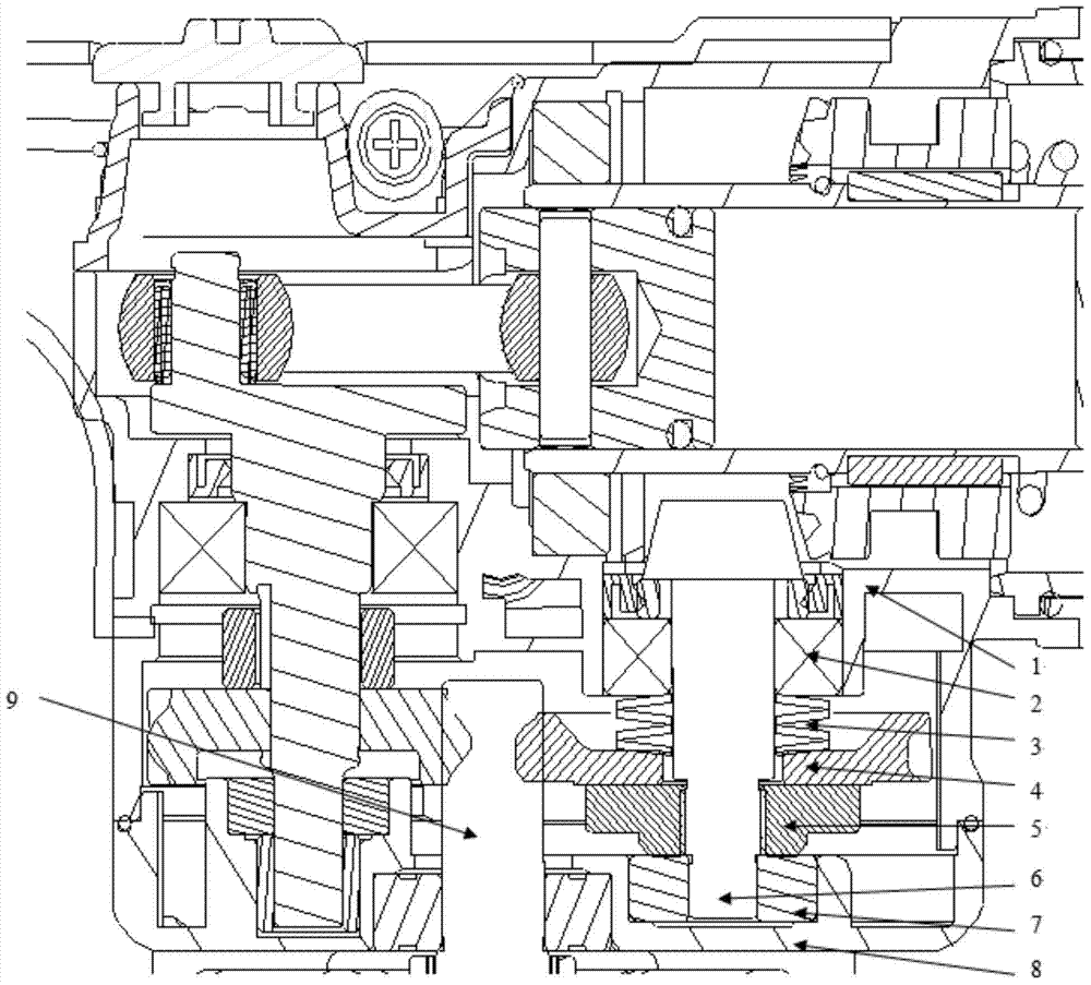
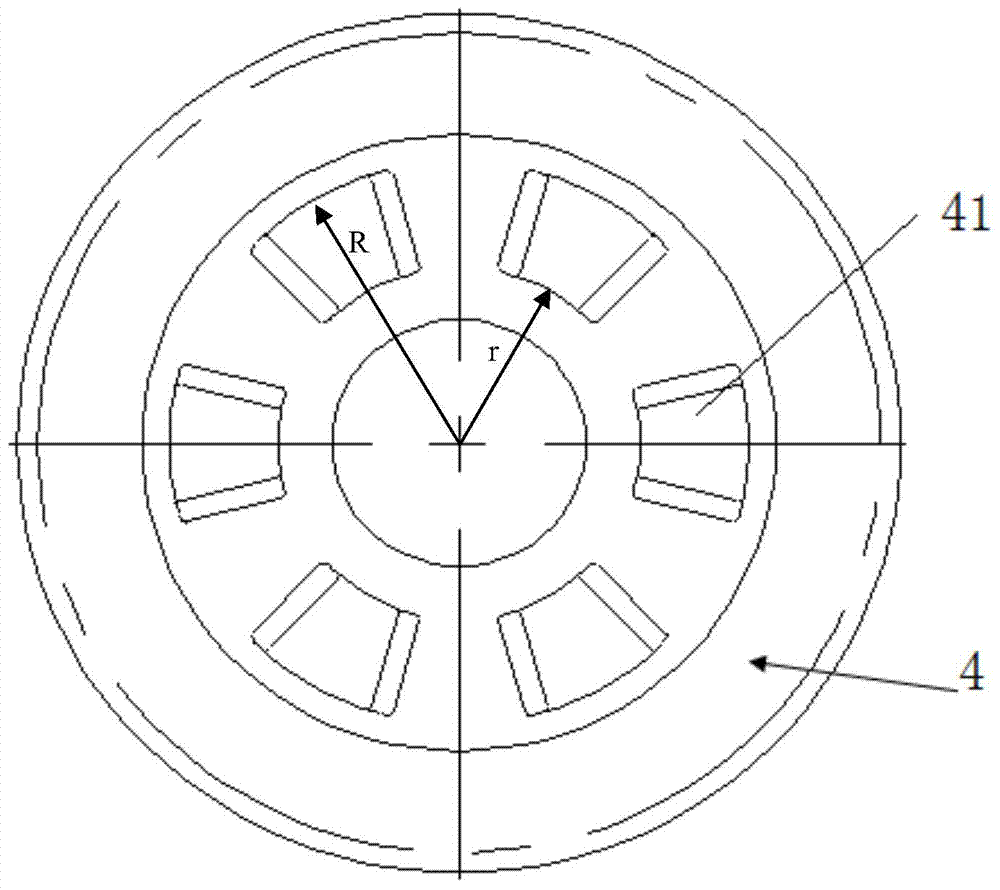
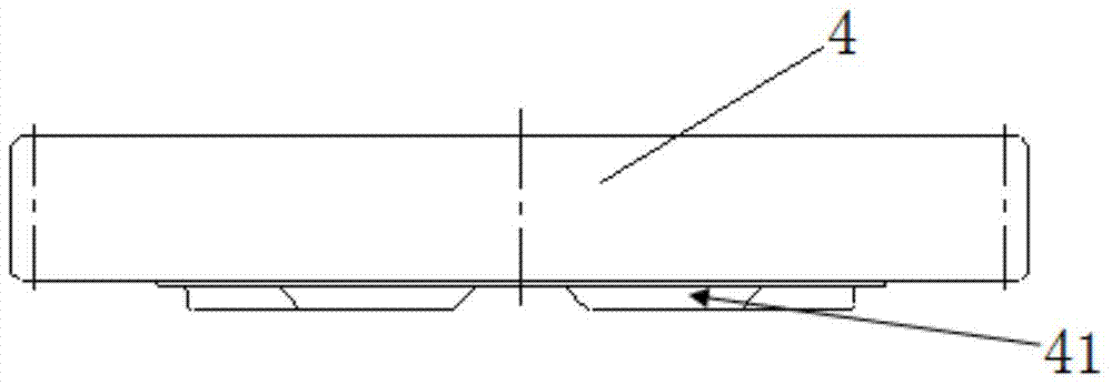
[0019] Such as Figure 1 to Figure 5 As shown, the clutch device of the electric tool includes: a reduction box 1, a second bearing 2 installed on the reduction box 1, a small shaft 6 passing through the second bearing 2, and a butterfly spring 3 is sleeved on the small shaft 6, The clutch gear 4 and the clutch block 5, the clutch block 5 and the small shaft 6 are screwed together, the clutch gear 4 is pressed on the clutch block 5 by the butterfly spring 3, and the clutch gear 41 and the clutch block 5 provided by the clutch gear 4 The clutch teeth 51 of the clutch block arranged on the top mesh with each other, the clutch gear 4 meshes with the gear of the armature 9 mounted on the middle cover 8 , and the small shaft 6 is fixed on the middle cover 8 through the first bearing 7 .

[0020] Such as figure 1 As shown, the armature 9 rotates, the gear meshes to drive the clutch gear 4, the clutch gear 4 drives the clutch block 5, and the clutch block 5 drives the small shaft 6 ...


PUM


Abstract

The invention discloses a clutch device of an electric tool. The clutch device comprises a reduction box and a middle cover covering the front side of the reduction box, wherein a small shaft passes through the front wall of the reduction box; a first bearing is arranged between the small shaft and the middle cover; a second bearing is arranged between the small shaft and the front wall of the reduction box; a disc spring, a separation and reunion gear and a separation and reunion block are sleeved in sequence between the second bearing and the first bearing on the small shaft; the separation and reunion block is fixed together with the small shaft; the separation and reunion gear is pressed onto the separation and reunion block through the disc spring; meshed separation and reunion teeth are arranged between the separation and reunion gear and the separation and reunion block; the separation and reunion gear is meshed with a gear of an armature arranged on the middle cover. The structural safety and reliability of the clutch device are enhanced.

Description

technical field [0001] The present invention relates to a clutch device, more specifically a clutch device used on an electric hammer. Background technique [0002] The clutch device installed on the electric hammer can prevent the large torque reaction force from being transmitted to the user due to the sticking of the drill bit during use, which is a kind of safety protection for the user. Moreover, this mechanism can also be used in the functional shifting of the mechanism to achieve the effect of effectively protecting the gears during shifting. The safety and reliability of the clutch device used on the electric hammer in the prior art needs to be improved. Contents of the invention [0003] The technical problem to be solved by the present invention is to provide a clutch device installed on an electric hammer to improve safety and reliability. [0004] In order to solve the above-mentioned technical problems, the present invention adopts the following technical so...

Claims


Application Information

Patent Timeline
Patent Type & Authority Patents(China)
IPC IPC(8): B25D17/10F16D9/00
Inventor 张勤业
Owner ZHEJIANG TONGDA ELECTRICAL APPLIANCE
Why Eureka
Try Eureka