Energy-saving vacuum pump of automobile

A vacuum pump and automobile technology, applied in the direction of pumps, pump components, rotary piston pumps, etc., can solve the problems of increasing the energy consumption of the engine and increasing the energy consumption of the vacuum pump.

Active Publication Date: 2021-09-10
淄博真空设备厂有限公司
View PDF7 Cites 2 Cited by
  • Summary
  • Abstract
  • Description
  • Claims
  • Application Information

AI Technical Summary

Problems solved by technology

Since the drive shaft of the engine drives the rotor of the vacuum pump of the car to rotate, the maximum vacuum degree is maintained in the booster, but the car does not need to brake all the time when it is workin

Method used


Image

  • Energy-saving vacuum pump of automobile
  • Energy-saving vacuum pump of automobile
  • Energy-saving vacuum pump of automobile

Examples


Embodiment Construction

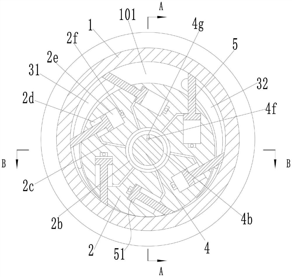
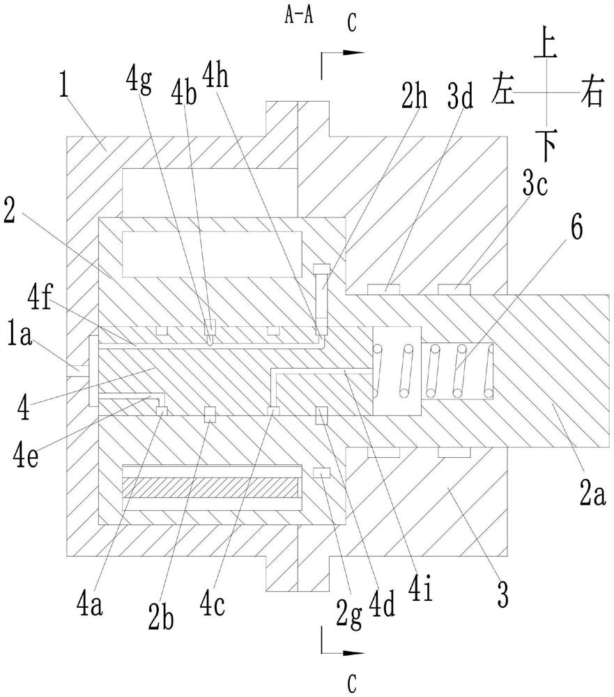
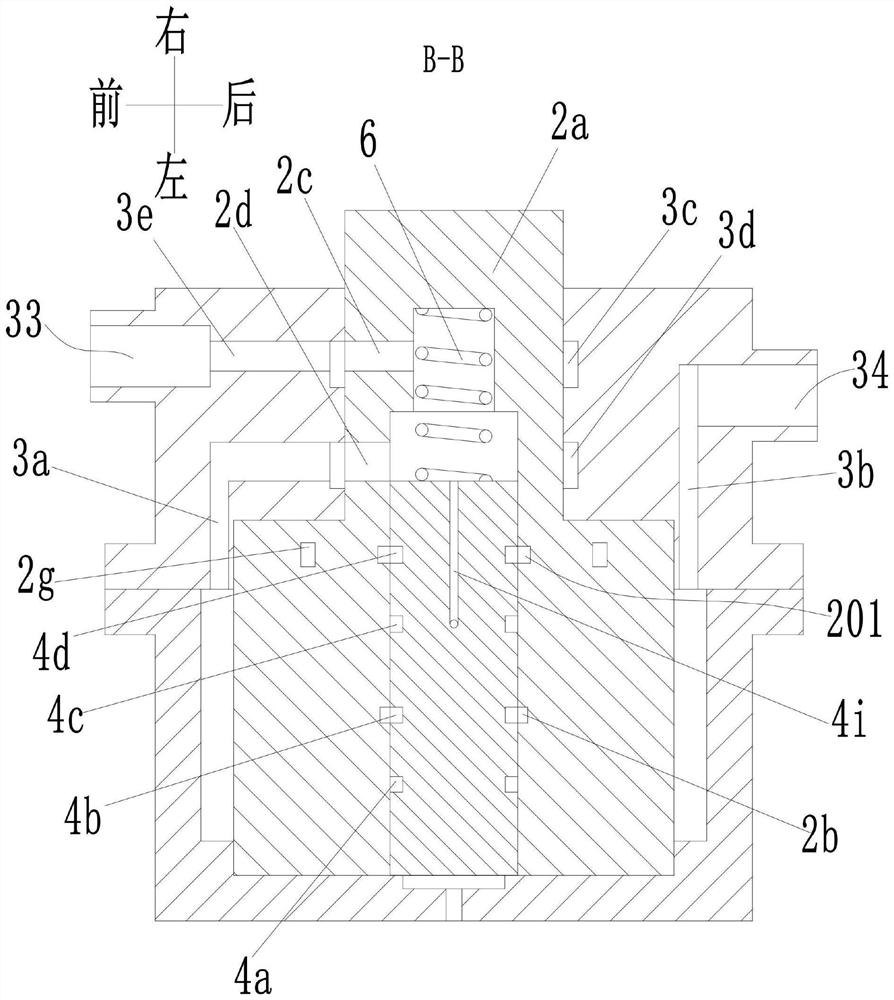
[0023] see Figure 1-7 As shown, an automobile energy-saving vacuum pump includes a pump body 1, a pump chamber 101 with an opening at the right end is arranged in the pump body 1, and an end block 3 is fixedly installed at the opening of the right end of the pump chamber 101 in the pump body 1. A rotor 2 is rotationally connected between the left end of the pump chamber 101 and the end block 3, and the rotor 2 is eccentrically arranged in the pump chamber 101; the right end of the rotor 2 is extended with a rotating shaft 2a protruding from the end block 3, The rotating shaft 2a and the rotor 2 are in a coaxial position; the rotor 2 is evenly provided with a plurality of chute 202 along the circumferential direction, and each chute 202 is slidably connected with a slider 51, and each slider 51 The vanes 5 for extending out of the rotor 2 are extended on the top, and the pump chamber 101 is provided with suction grooves 31 and air outlet grooves 32 symmetrically on both sides ...


PUM


Abstract

The invention discloses an energy-saving vacuum pump of an automobile. The energy-saving vacuum pump comprises a pump body, a pump cavity is formed in the pump body, an end block is fixedly mounted in the position, at an opening in the right end of the pump cavity, of the pump body, and a rotor is rotationally connected between the left end of the pump cavity and the end block; a rotating shaft extending out of the end block is arranged at the right end of the rotor in an extending mode; a plurality of sliding grooves are evenly formed in the rotor in the circumferential direction at intervals, a sliding block is connected into each sliding groove in a sliding mode, and a blade extending out of the rotor is arranged on each sliding block in an extending mode; an air suction groove and an air outlet groove are symmetrically formed in the two sides of the rotor in the pump cavity, an air suction opening communicating with the air suction groove and an air outlet communicating with the air outlet groove are formed in the outer side of the end block; shaft holes are formed in the rotor and the rotating shaft in the axial direction of the rotating shaft, and plungers are arranged in the shaft holes in the left-right direction. The energy-saving vacuum pump of the automobile is simple in structure, and when the vacuum degree of the air suction opening reaches a set value, the vacuum pump loses efficacy, so that the energy consumption is reduced.

Description

technical field [0001] The invention relates to the technical field of vacuum pumps, in particular to an automotive energy-saving vacuum pump. Background technique [0002] The car vacuum pump is directly connected with the drive shaft of the engine, and the drive shaft of the engine drives the rotor of the vacuum pump to run. The air inhaled by the suction port is compressed in the inner cavity of the pump body, and discharged from the air outlet, thereby generating vacuum suction for the car brake. Since the drive shaft of the engine drives the rotor of the vacuum pump of the car to rotate, the maximum vacuum degree is maintained in the booster, but the car does not need to brake all the time when it is working normally, so it is not necessary to maintain the vacuum degree in the booster at a high level. Level, which will increase the energy consumption of the vacuum pump and increase the energy consumption of the engine. Contents of the invention [0003] The object of...

Claims


Application Information

Patent Timeline
IPC IPC(8): F04C18/344F04C25/02F04C28/00
CPCF04C18/3441F04C25/02F04C28/00F04C29/00F04C2240/20
Inventor 王丽娜程建军刘欣
Owner 淄博真空设备厂有限公司
Why Eureka
Try Eureka