
Rotor wing tilting mechanism, tilting rotor wing hovercar and flying device

A technology of rotor tilting and flying cars, which is applied in the direction of rotorcraft, vehicles that can be converted into airplanes, aircraft, etc., and can solve problems that affect the rotor mode and fixed-wing conversion

Inactive Publication Date: 2021-09-10
GUANGDONG HUITIAN AEROSPACE TECH CO LTD
View PDF10 Cites 2 Cited by
  • Summary
  • Abstract
  • Description
  • Claims
  • Application Information

AI Technical Summary

Problems solved by technology

[0003] However, the existing tilt mechanism cannot smoothly control the tilt angle of the rotor, which affects the conversion between the rotor mode and the fixed wing mode

Method used


Image

  • Rotor wing tilting mechanism, tilting rotor wing hovercar and flying device
  • Rotor wing tilting mechanism, tilting rotor wing hovercar and flying device
  • Rotor wing tilting mechanism, tilting rotor wing hovercar and flying device

Examples


Embodiment Construction

[0030] To facilitate understanding of the embodiments of the present invention, the following embodiments with reference to the accompanying drawings related to embodiments of the present invention will be more fully described. The preferred embodiment of the present invention is given in the drawings. However, the present invention can be implemented in many different forms, is not limited to the embodiments described herein. Conversely, the purpose of providing these embodiments is to make a more thorough understanding of the disclosure of the present invention.

[0031] All techniques and scientific terms used herein are identical to those skilled in the art, unless otherwise defined. The term as used herein in the embodiment of the present invention is only for the purpose of describing particular embodiments and are not intended to limit the invention.

[0032] The inventors of the present application has found that the existing design of drive mechanism mainly tilting servo ...


PUM


Abstract

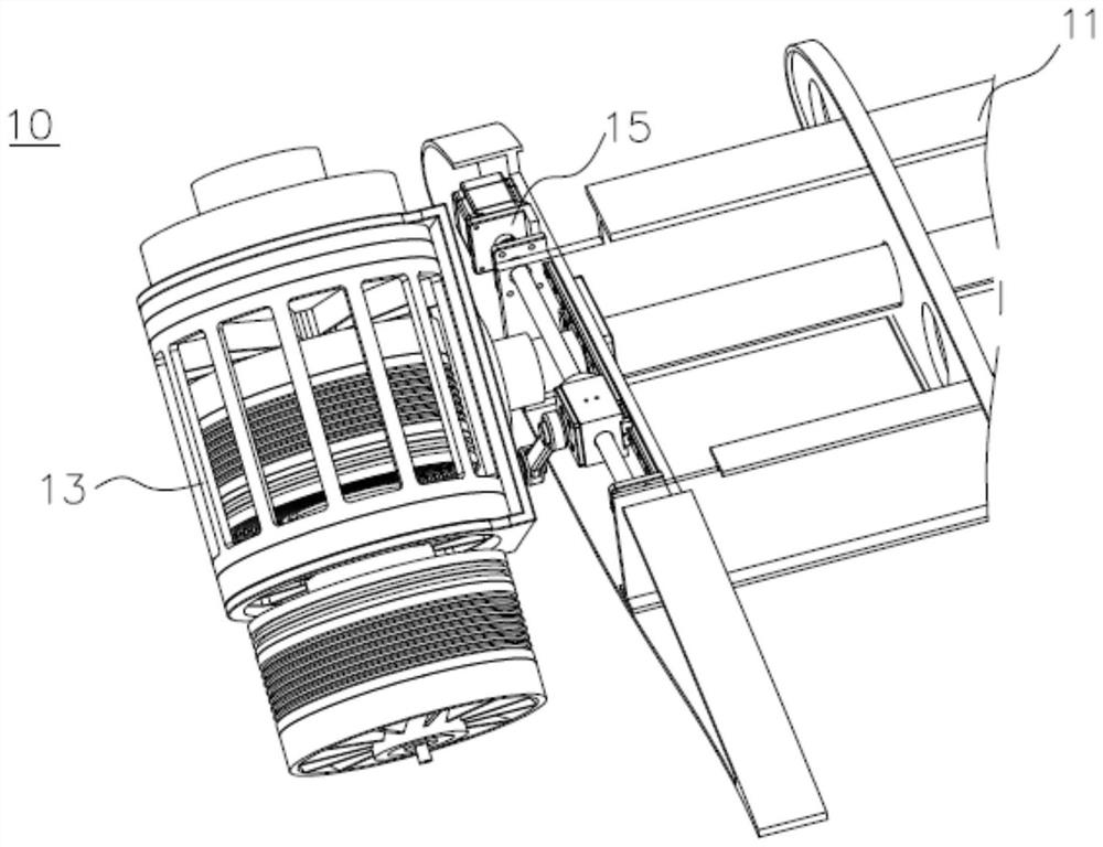
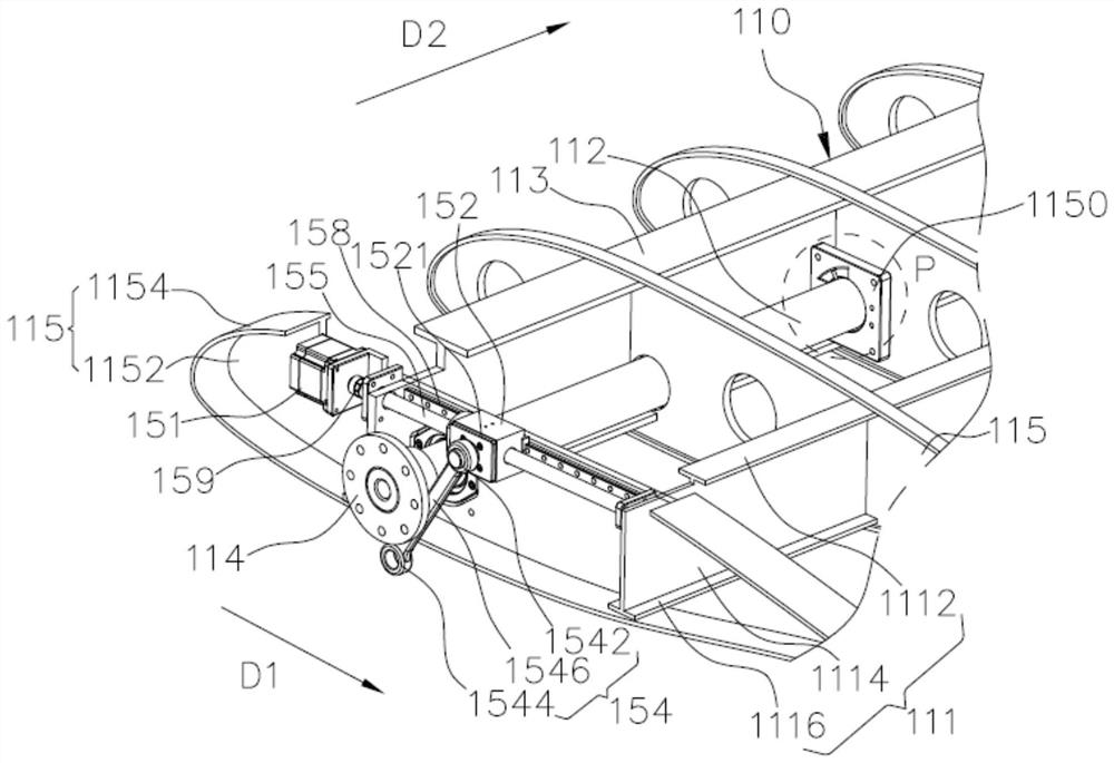
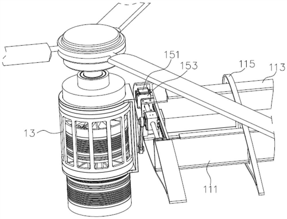
The invention provides a rotor wing tilting mechanism. The rotor wing tilting mechanism comprises a wing assembly, a power assembly and a tilting assembly. The wing assembly comprises a wing main body and a rotor wing tilting shaft, and the rotor wing tilting shaft is rotatably arranged on the wing main body; the power assembly comprises a rotor motor and a motor fixing base, the rotor motor is arranged on the motor fixing base, and the motor fixing base is connected to the rotor tilting shaft; the tilting assembly comprises a driving part, a sliding part and a connecting part, the driving part is fixed to the wing body, the driving part is in transmission connection with the sliding part to drive the sliding part to slide, and the connecting part is movably connected between the sliding part and the motor fixing base so as to drive the power assembly to rotate through the sliding part; and the sliding part, the connecting part and the motor fixing base form a slider-crank mechanism. According to the rotor wing tilting mechanism provided by the invention, the sliding part, the connecting part and the motor fixing base form the slider-crank mechanism so that the tilting angle of the rotor wing can be stably controlled. The invention further provides a tilting rotor wing hovercar and a flying device.

Description

Technical field [0001] The present invention relates to the technical field of flight device, particularly, to a rotor tilting mechanism, and the tiltrotor flying car flying device. Background technique [0002] Tiltrotor technology combines the advantages of fixed-wing and rotary-wing, capable of tilting through a motor rotor, conversion between the rotor and fixed-wing flight status flight status, VTOL capability of both the rotor, and both fixed wing the advantages of high-speed flight. In the tilt-rotor technology, one of the core part is tilting mechanism. [0003] However, the conventional tilting mechanism can not be smoothly controlled tilting angle of the rotor, affecting the transition between the rotor and fixed wing modes mode. Inventive content [0004] Object of embodiments of the present invention to provide a rotor tilting mechanism, tiltrotor flying car or flying device, in order to improve the above problems. The above object is achieved by the embodiment of th...

Claims


Application Information

Patent Timeline
IPC IPC(8): B64C27/52B64C27/28B60F5/02
CPCB64C27/52B64C27/28B60F5/02
Inventor 王谭徐厚超刘波
Owner GUANGDONG HUITIAN AEROSPACE TECH CO LTD
Learn More