Rotating body position detection device
A detection device and a rotating body technology, applied in the detection field, can solve the problems of large axial space and occupation of magnetic encoders, etc.
- Summary
- Abstract
- Description
- Claims
- Application Information
AI Technical Summary
Problems solved by technology
Method used
Image

Examples
Embodiment 1
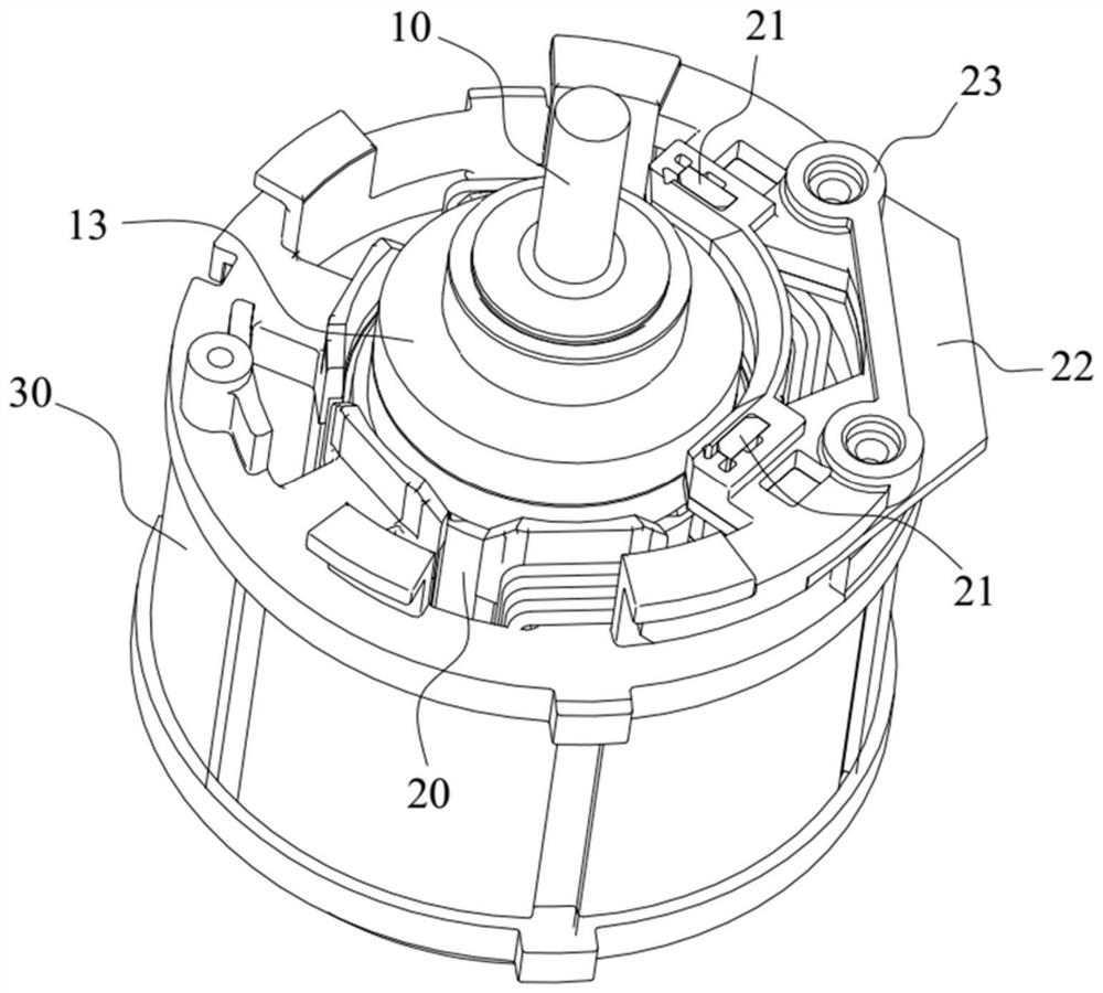
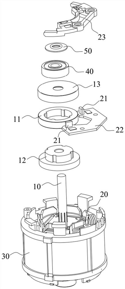
[0039] See Figures 1 to 7 , The embodiment of the present invention provides a rotating body position detecting device, which can detect the position of the rotor. Here, the rotating body can be a rotating body having a central axis and can rotate about the center axis, such as a motor rotor 10 or other rotating member.
[0040] The rotating body position detecting means includes a magnetic ring 11, a computing unit, and at least two Hall sensors 21, and the magnetic ring 11 is fixed to the rotating body, and the magnetic ring 11 includes at least one pair of magnetic poles, the magnetic pole is radially distributed along the magnetic ring 11. In the present embodiment, the Hall sensor 21 is disposed at intervals of the outer circumferential surface of the magnetic ring 11 for detecting the magnetic field strength of the outer surface of the magnetic ring 11; the calculation unit is used to calculate the magnetic field strength calculated according to each Hall sensor 21. The posi...
Embodiment 2
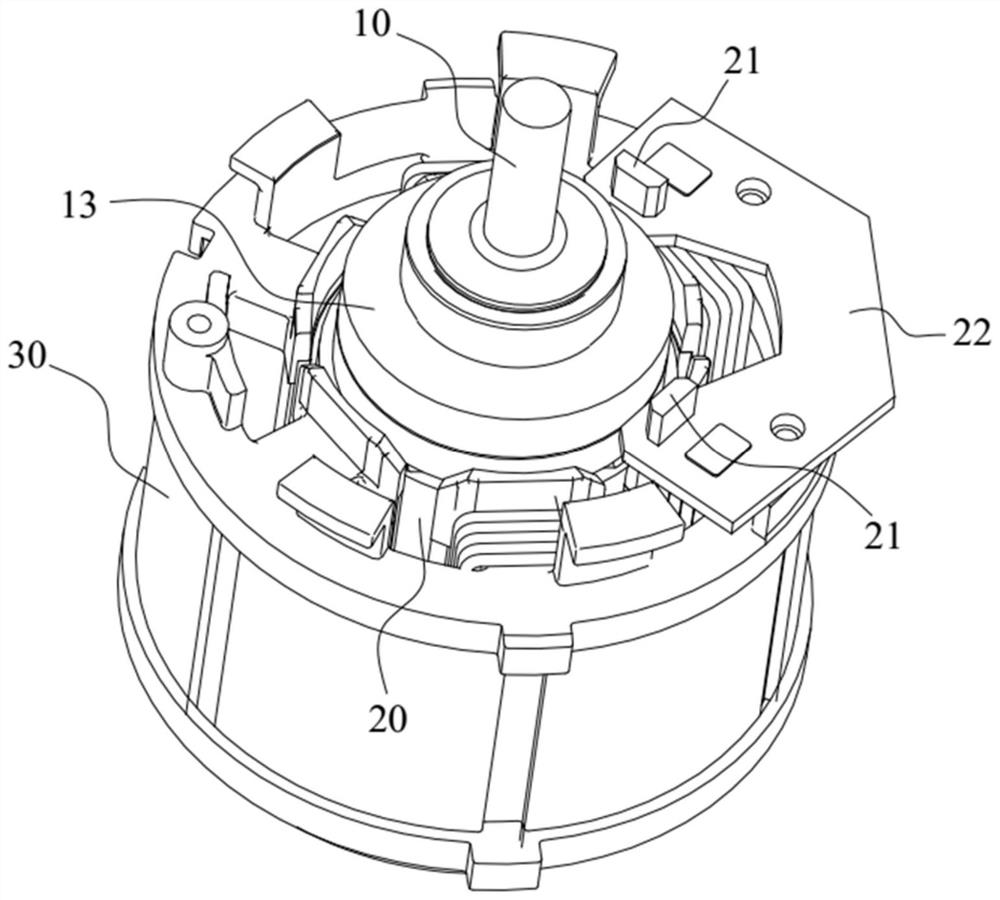
[0057] Figure 8 to 10 The second embodiment is shown, wherein the same or corresponding components as the embodiments are marked with reference to the embodiments. For the sake of simplicity, only the difference points of the second embodiment and the embodiment one are described. The difference is that the circuit board 22 is ringing in the outer circumference of the magnetic ring 11 such that the circuit board 22 avoids the vents of the wire slots on the motor, facilitating the electric heat dissipation.
[0058] A legs are provided on the circuit board 22, and there is a mounting hole on the feet. The pins are fixedly connected to the housing 30 of the motor through the fastener, and the fasteners are in the mounting hole. In the present embodiment, four pins are provided around the circuit board 22, and one mounting hole is opened on each leg.
[0059] In the present embodiment, the sensor support frame 23 is enabled in the outer circumference of the Hall sensor 21, which is ...
Embodiment 3
[0063] For the sake of simplicity, only the difference points of the third embodiment and the embodiment one are described. The difference is that at least two Hall sensors 21 are disposed on the end surface of the magnetic ring 11 for detecting the magnetic field strength of the end face of the magnetic ring 11; the calculation unit is used to calculate the magnetic field strength calculated according to each Hall sensor 21 The position of the body.
[0064] When the rotating body is rotated about the central axis, the magnetic ring 11 is rotated, and the Hall sensor 21 can detect the magnetic field strength of the end face of the magnetic ring 11, in which the position of the rotating body can be detected. The Hall sensor 21 takes up a small space, facilitates the spatial layout, making the axial structure compact. The spatial position of the rotating body can be obtained by the signal output by the Hall sensor 21, which is easy to control.
[0065] Specifically, the two Hall se...
PUM
 Abstract
Description
Claims
Application Information
 - R&D
- Intellectual Property
- Life Sciences
- Materials
- Tech Scout
- Unparalleled Data Quality
- Higher Quality Content
- 60% Fewer Hallucinations
Browse by: Latest US Patents, China's latest patents, Technical Efficacy Thesaurus, Application Domain, Technology Topic, Popular Technical Reports.
© 2025 PatSnap. All rights reserved.Legal|Privacy policy|Modern Slavery Act Transparency Statement|Sitemap|About US| Contact US: help@patsnap.com