Reactive power control method and system for power distribution network
A distribution network and power control technology, which is applied in the direction of single-network parallel feed arrangement, etc., can solve the problems that affect the effect of reactive power control and cannot guarantee the ability of reactive power adjustment
- Summary
- Abstract
- Description
- Claims
- Application Information
AI Technical Summary
Problems solved by technology
Method used
Image

Examples
Embodiment 1
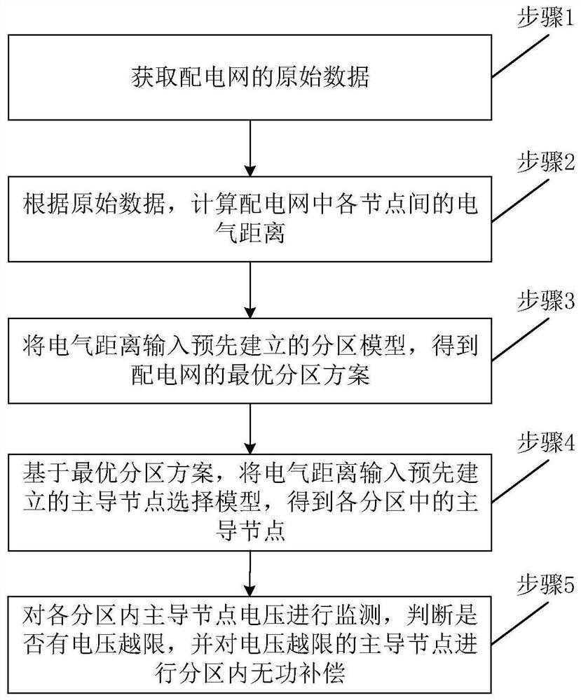
[0076] A schematic flow chart of a reactive power control method for a distribution network provided by the present invention is as follows figure 1 shown, including:
[0077] Step 1: Obtain the raw data of the distribution network; specifically include:
[0078] Input the original data of the power distribution network that needs to be partitioned, including network parameters such as transformer and line impedance, capacity of parallel reactive power compensation device, active and reactive load data of each node, number of required partitions, and solution algorithm parameters. The source of the original data can be obtained through effective measurement means, and the power flow calculation can be performed on the distribution network that needs to be partitioned.
[0079] Step 2: According to the original data, calculate the electrical distance between each node in the distribution network, the nodes include load nodes and reactive power sources; specifically include:
...
Embodiment 2
[0124] The simulation calculation is carried out in the IEEE 33-node power distribution system, the system reference voltage is 12.66kV, and the reference capacity is 10MVA. The network structure of high-penetration photovoltaic access to 33-node distribution network Figure 4 , distributed power sources are respectively connected to nodes 7, 10, 13, 15, 17, 19, 23, 26, 28, and 31 as reactive power sources, and other nodes are load nodes; the capacity of distributed power sources is 0.1p.u.; The photovoltaic penetration rate of the power grid is 50%; the number of partitions k=3; the weight coefficient of the regional reactive power balance redundancy index of the distribution network partition index is 0.5, and the weight coefficient of the coupling degree index inside and outside the region is 0.25, that is, α 1 = 0.5, α 2 = α 3 = 0.25; the weight coefficients of controllability index and observability index of distribution network dominant node selection index are both 0....
Embodiment 3
[0131] Based on the same inventive concept, the present invention also provides a distribution network reactive power control system. Since the principle of these devices to solve technical problems is similar to that of the distribution network reactive power control method, repeated descriptions will not be repeated here.
[0132] The basic structure of the system is as Figure 6 As shown, including: data acquisition module, electrical distance module, grid partition module, leading node module and reactive power compensation module;
[0133] Among them, the data acquisition module is used to obtain the original data of the distribution network;
[0134] The electrical distance module is used to calculate the electrical distance between nodes in the distribution network according to the original data, and the nodes include load nodes and reactive power sources;
[0135] The power grid partition module is used to input the electrical distance into the pre-established partiti...
PUM
 Abstract
Description
Claims
Application Information
 - R&D
- Intellectual Property
- Life Sciences
- Materials
- Tech Scout
- Unparalleled Data Quality
- Higher Quality Content
- 60% Fewer Hallucinations
Browse by: Latest US Patents, China's latest patents, Technical Efficacy Thesaurus, Application Domain, Technology Topic, Popular Technical Reports.
© 2025 PatSnap. All rights reserved.Legal|Privacy policy|Modern Slavery Act Transparency Statement|Sitemap|About US| Contact US: help@patsnap.com