


Quick Research
Generate reliable direction feasibility study reports for your R&D in just a few steps.

Technical Q&A
Discover and master advanced knowledge NOW. Basics, ideas, possibilities, all at once.

Find Solutions
As an expert in R&D theories, this can generate solutions to your technical problems instantly.

Evaluate Feasibility
Analyze your overall solution with one click, know your potential R&D risks in advance.

Monitor Landscape
Get weekly tech updates, stay abreast of the latest tech innovations and key insights.
Ball screw pair transmission device and method capable of achieving automatic pre-tightening
A ball screw pair and transmission technology, which is applied to the transmission, transmission parts, belt/chain/gear, etc., can solve the problems such as affecting the transmission accuracy of the ball screw pair, unable to use manual manual adjustment, affecting the work progress, etc.
- Summary
- Abstract
- Description
- Claims
- Application Information
AI Technical Summary
Problems solved by technology
Method used
Image

Examples
Embodiment 1
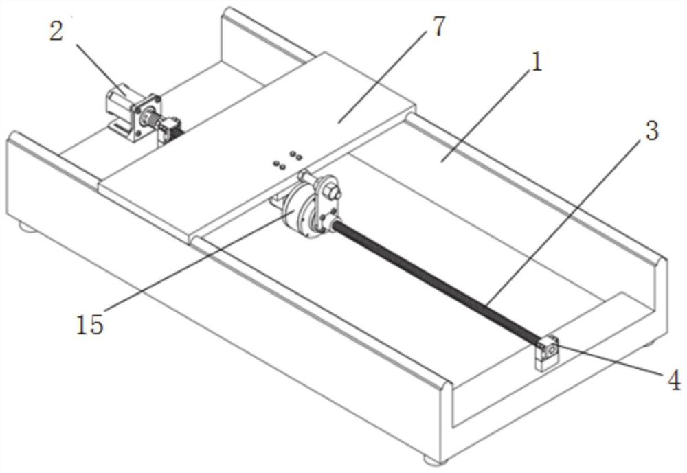
[0032] A ball screw pair transmission device capable of automatic preload, such as figure 1 As shown, a base 1 is included, and the base adopts a U-shaped structure, including a first base part arranged horizontally and a second base part vertically fixed at both ends of the first base part. The base is used as a supporting part for each element of the entire transmission system, and can be installed on the relevant supporting mechanism of the equipment used according to actual needs during use.
[0033] A ball screw pair is installed on the first base part, and the ball screw pair can adopt an existing ball screw structure, including a driving part, and the driving part is used as a power supply device for the ball screw pair. In one embodiment, the driving part is a stepping motor 2, the output shaft of the stepping motor is connected to the lead screw 3 through a coupling, and the stepping motor can drive the rotation of the lead screw.
[0034] In order to ensure the rota...
Embodiment 2
[0064] This embodiment discloses a method for preloading the automatic preloading ball screw transmission described in Embodiment 1:
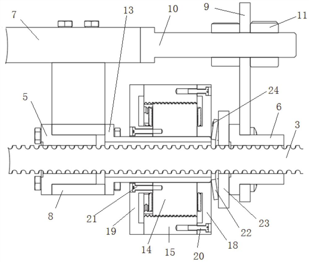
[0065] The coil is connected to the power supply through the connecting wire, the coil is energized, a magnetic field force is generated between the coil and the magnet, and the magnetic field force drives the rotor to rotate around its own axis. When the rotor rotates, the rotor moves along the axis of the screw, and the rotor passes through the first end cover. Squeeze the butterfly spring, the butterfly spring exerts a reaction force, the reaction force acts on the main nut and the auxiliary nut, and exerts a pretightening force on the main nut and the auxiliary nut, so as to eliminate the transmission gap between the main nut and the auxiliary nut.
[0066] The whole process of adjusting the pretightening force does not require manual operation, which saves time and labor, and has high work efficiency.
[0067] During the working process of...
PUM
 Abstract
Description
Claims
Application Information
 - R&D Engineer
- R&D Manager
- IP Professional
- Industry Leading Data Capabilities
- Powerful AI technology
- Patent DNA Extraction
Browse by: Latest US Patents, China's latest patents, Technical Efficacy Thesaurus, Application Domain, Technology Topic, Popular Technical Reports.
© 2024 PatSnap. All rights reserved.Legal|Privacy policy|Modern Slavery Act Transparency Statement|Sitemap|About US| Contact US: help@patsnap.com