Loading device and method for asymmetric cyclic load of tested piece

A cyclic load and loading device technology, applied in measuring devices, using repetitive force/pulsation force to test the strength of materials, instruments, etc. The effect of reducing trial costs

Active Publication Date: 2020-05-22
JILIN UNIV
View PDF7 Cites 0 Cited by
  • Summary
  • Abstract
  • Description
  • Claims
  • Application Information

AI Technical Summary

Problems solved by technology

This method has the following disadvantages: an additional static loading device is required, which increases the cost of the experiment; the connection between the end of the specimen and the static loading device will change the force impedance of the specimen and reduce the experimental efficiency

Method used


Image

  • Loading device and method for asymmetric cyclic load of tested piece
  • Loading device and method for asymmetric cyclic load of tested piece
  • Loading device and method for asymmetric cyclic load of tested piece

Examples


Embodiment Construction

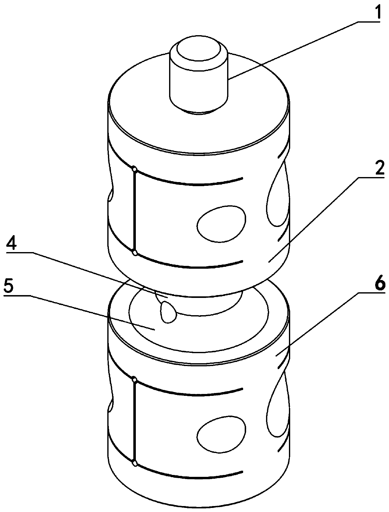
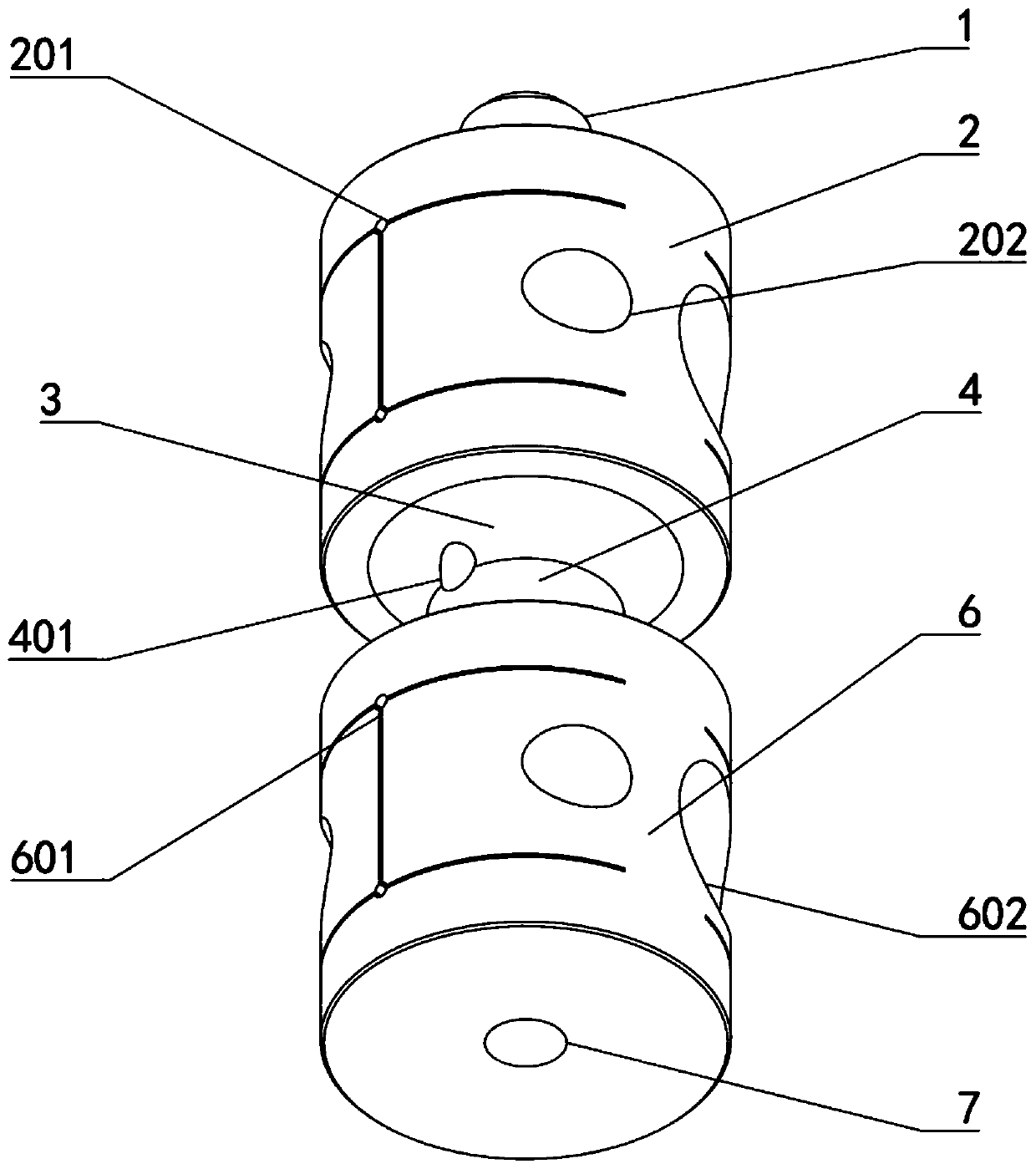
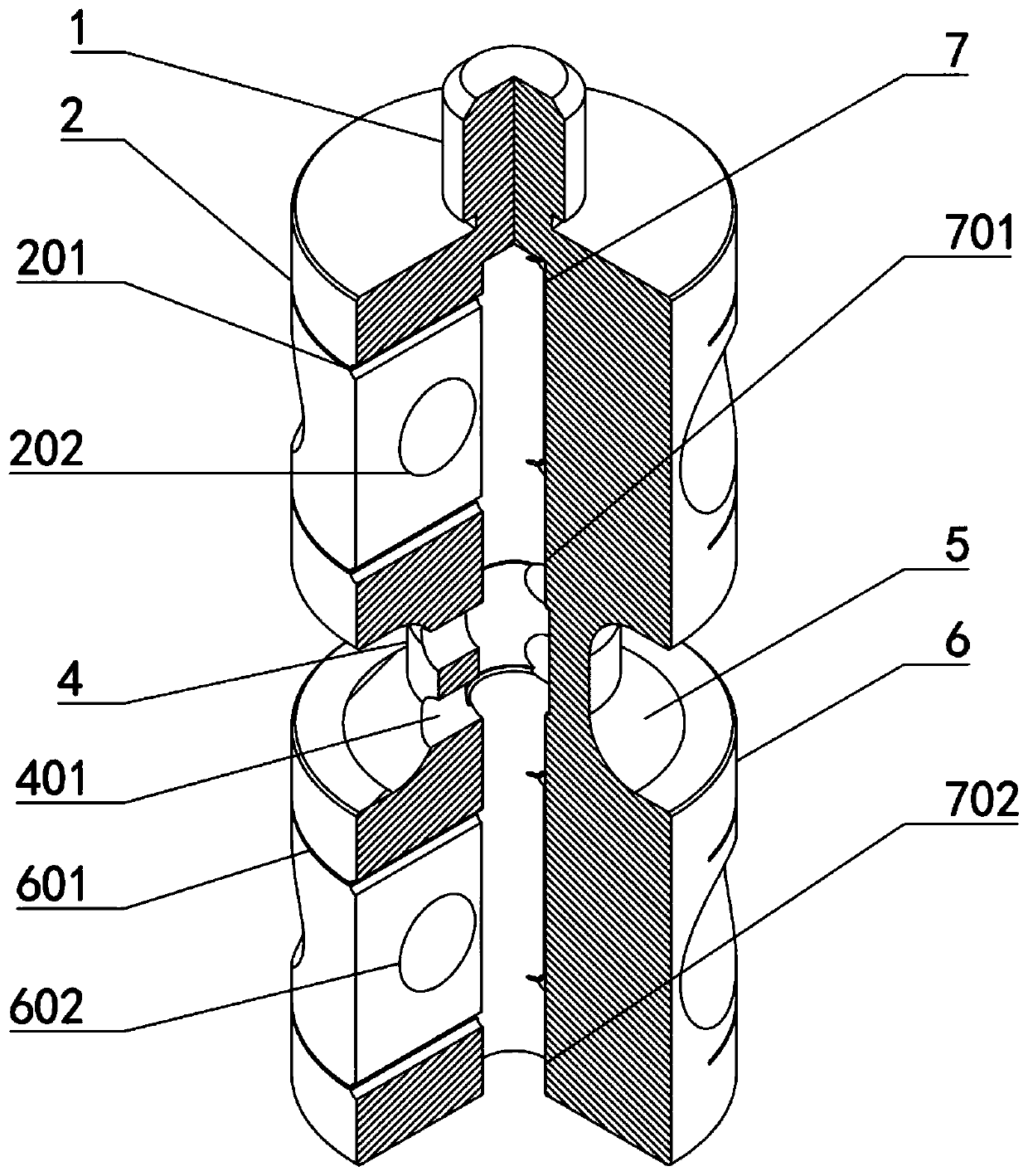
[0035] like figure 1 , figure 2 As shown, it includes connecting column 1, upper specimen clamping end 2, upper catenary transition section 3, middle section 4, lower catenary transition section 5, lower specimen clamping end 6 and specimen mounting hole 7, Wherein the connecting column 1 is connected with the top of the clamping end 2 of the upper test piece, the clamping end 2 of the upper test piece is connected to the upper catenary transition section 3, and the upper catenary transition section 3 is connected to the middle section 4. The bottom of the section 4 is connected to the lower catenary transition section 5;

[0036] The connecting column 1, the upper specimen clamping end 2, the upper catenary transition section 3, the middle section 4, the lower catenary transition section 5, and the lower specimen clamping end 6 are coaxial to ensure that the mechanical vibration is only along the Longitudinal transmission to avoid the occurrence of lateral vibration;

[0...


PUM


Abstract

The invention relates to a loading device and method for an asymmetric cyclic load of a tested piece, and belongs to the field of ultrasonic loading. A connecting column is connected to the top of anupper test piece clamping end, the upper test piece clamping end is connected to an upper catenary transition section downwards, the upper catenary transition section is connected to a middle sectiondownwards, the bottom of the middle section is connected to a lower catenary transition section, the lower catenary transition section is connected to a lower test piece clamping end, and a test piecemounting hole is located inside the lower part of the connecting column. The device has the advantages of novel structure, relatively few processes, easy machining, stable structure, and good test performance and stability, and is suitable for different test machines, realizes that the adjustment range r of the cycle characteristics is greater than -1 and smaller than 1, is beneficial to focusingof vibration energy in vibration test, reduces energy loss, and provides convenience for test data collection.

Description

technical field [0001] The invention relates to the field of ultrasonic loading in the field of engineering technology, in particular to an auxiliary device and method for loading and adjusting the initial prestress of a tested piece of an ultrasonic fatigue testing machine in a mechanical fatigue test. Background technique [0002] In the field of modern engineering, many important parts work under the action of alternating stress, and fatigue damage caused by alternating loads has become the main failure form of most parts. Due to the limitations of test equipment and test conditions, the range of stress cycles in traditional material fatigue test research is limited to 10 7 within times. However, in modern engineering, especially in the field of high-tech engineering, many engineering components work under the condition of small alternating load and high alternating frequency, and the number of alternating times these parts bear is much higher than 10 7 times, sometimes...

Claims


Application Information

Patent Timeline
IPC IPC(8): G01N3/32G01N3/62G01N3/02G01N3/04
CPCG01N3/02G01N3/04G01N3/32G01N3/62G01N2203/0005G01N2203/0055G01N2203/0423
Inventor 王昕张学成曹晓东张瀚冰李文权李群姜冬梅
Owner JILIN UNIV
Why Eureka
Try Eureka