
Laser marking equipment

A laser marking and laser marking technology, which is applied to laser welding equipment, welding equipment, metal processing equipment, etc., can solve the problems of increasing workload and reducing work efficiency, and achieve the effects of avoiding friction, protecting thoroughly, and improving marking efficiency

Active Publication Date: 2021-09-07
上海首坤智能科技有限公司
View PDF13 Cites 4 Cited by
  • Summary
  • Abstract
  • Description
  • Claims
  • Application Information

AI Technical Summary

Problems solved by technology

[0002] The existing laser marking equipment needs to be manually adjusted when the product has a shape and pattern, which increases the workload and reduces the work efficiency

Method used


Image

  • Laser marking equipment
  • Laser marking equipment
  • Laser marking equipment

Examples


Embodiment 1

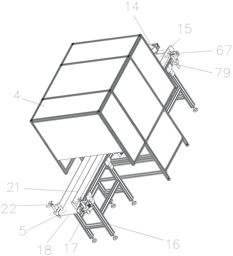
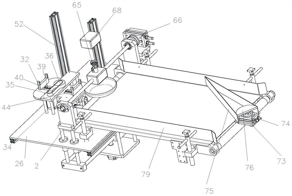
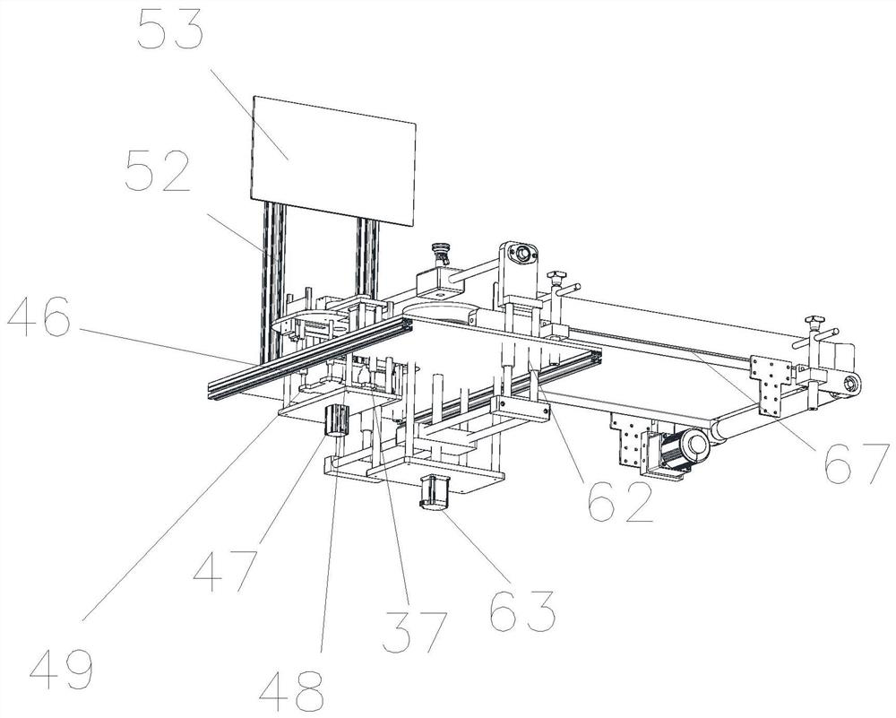
[0030] Embodiment 1 refers to appended Figure 1-13 , laser marking equipment, including a feeding device, a product identification device 11 and a laser marking device 68, one end of the feeding device is a feeding port 5, and the other end is a first transfer port 6, and a laser marking device is provided behind the first transfer port device, a connection and diversion device 3 is provided behind the laser marking device, a positioning turntable is provided between the first transfer port and the laser marking device, and a conveying device 9 for transporting products from the first transfer port to the positioning turntable and then to the laser marking device , the side of the positioning turntable is provided with a product identification device, and the feeding device includes a feeding bracket 16, a first transmission motor 17, a conveyor belt assembly 16, an inclined baffle 21 and an L-shaped support frame 1, and one end of the L-shaped support frame is a vertical sect...


PUM


Abstract

The invention provides laser marking equipment. One end of a feeding device is a feeding opening; the other end of the feeding device is a first transferring opening; a laser marking device is arranged behind the first transferring opening; a connecting and shunting device is arranged behind the laser marking device; a positioning rotary table and a conveying device for conveying products from the first transferring opening to the positioning rotary table and then conveying the products to the laser marking device are arranged between the first transferring opening and the laser marking device; and a product identification device is arranged on the side of the positioning rotary table. The laser marking equipment has the advantages that the products are thoroughly protected, the safety is high, the orientations of the products are automatically adjusted by recognizing the shapes and the pattern orientations of the products, the laser marking equipment is used for marking according to the patterns and the orientations, and the marking efficiency is improved.

Description

technical field [0001] The invention relates to a laser marking device. Background technique [0002] The existing laser marking equipment needs to be manually adjusted when the product has a shape and pattern, which increases the workload and reduces the work efficiency. Contents of the invention [0003] The object of the present invention is to solve the shortcomings in the prior art, and propose a laser marking device. [0004] In order to achieve the above object, the present invention adopts the following technical scheme: laser marking equipment, including a feeding device, a product identification device and a laser marking device, one end of the feeding device is a feeding port, the other end is a first transfer port, the first There is a laser marking device behind the transfer port, and a connecting and diverting device behind the laser marking device. There is a positioning turntable between the first transfer port and the laser marking device, and the transpo...

Claims


Application Information

Patent Timeline
Patent Type & Authority Applications(China)
IPC IPC(8): B65G47/248B65G47/91B65G47/24B23K26/362B23K26/70B23K26/03B07C5/34
CPCB65G47/248B65G47/918B65G47/24B23K26/362B23K26/702B23K26/032B07C5/34
Inventor 王文茜刘猛军
Owner 上海首坤智能科技有限公司
Learn More