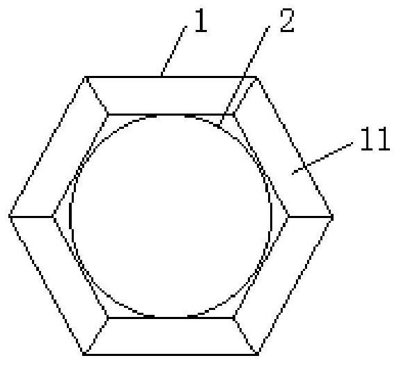
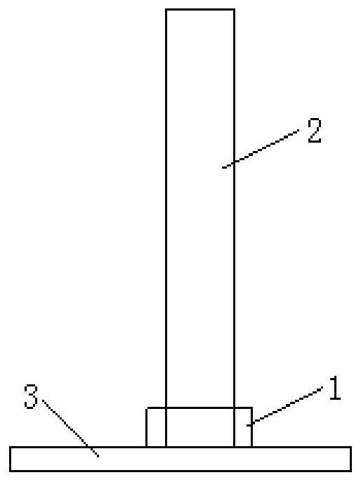
Pipe body subsection connection device and method

A technology for connecting devices and pipe bodies, applied in auxiliary devices, welding equipment, auxiliary welding equipment, etc., can solve the problems of expensive equipment, flange reliability, extremely high fatigue characteristics, and complex procedures, and achieve reduced requirements. , The effect of ensuring the continuity and reliability of the overall structure and reducing costs

Pending Publication Date: 2021-09-07
XIAERTELA ENERGY CO LTD
View PDF0 Cites 0 Cited by
  • Summary
  • Abstract
  • Description
  • Claims
  • Application Information

AI Technical Summary

Problems solved by technology

This traditional connection method, due to the existence of flanges on each pipe body segment, destroys the overall structural continuity of the pipe body after the connection is completed. In order to ensure the integrity of the pipe body structure as a whole, it is necessary to make the flange It is very strong and welded to the end of the pipe body segment. It has extremely high requirements on the reliability and fatigue characteristics of the flange, and even requires special forgings to meet the requirements. The cost is high, the equipment is expensive, and the process is complicated.
At the same time, the connection to the flange is connected by high-strength bolts. The bolts are subjected to loads of different amplitudes for a long time, and there is a risk of loosening. The fatigue life and reliability of the bolts are extremely high.

Method used


Image

  • Pipe body subsection connection device and method
  • Pipe body subsection connection device and method
  • Pipe body subsection connection device and method

Examples


Embodiment Construction

[0026] The specific implementation manners of the present invention will be described in further detail below in conjunction with the accompanying drawings. These embodiments are only used to illustrate the present invention, not to limit the present invention.

[0027] In the description of the present invention, it should be noted that the terms "center", "longitudinal", "transverse", "upper", "lower", "front", "rear", "left", "right", " The orientations or positional relationships indicated by "vertical", "horizontal", "top", "bottom", "inner", "outer", etc. are based on the orientation or positional relationships shown in the drawings, and are only for the convenience of describing the present invention and simplifying Describes, but does not indicate or imply that the device or element referred to must have a specific orientation, be constructed in a specific orientation, and operate in a specific orientation, and therefore should not be construed as limiting the inventio...


PUM


Abstract

The invention relates to the technical field of pipe body subsection connection, in particular to a pipe body subsection connection device which comprises an annular operation platform. The annular operation platform detachably surrounds the peripheral face of a pipe body subsection, and the annular operation platform can ascend and descend in the axial direction of the pipe body subsection and stay at a designated position; and the annular operation platform bears operators and welding equipment. The invention further relates to a pipe body subsection connection method adopting the device. The pipe body subsection connection method mainly comprises the steps that the annular operation platform surrounds the peripheral face of the pipe body subsection which is vertically placed, so that the annular operation platform bears the operators and the welding equipment to ascend in the axial direction of the pipe body subsection and stay at the operation position; and a next pipe body subsection is vertically hoisted to the position above the previous pipe body subsection, the two pipe body subsections are welded through the welding equipment by the operators, and all the pipe body subsections are sequentially welded one by one. The cost can be greatly reduced, the requirement for installation and operation precision is lowered, and the continuity and reliability of the whole structure of a pipe body are improved and ensured.

Description

technical field [0001] The invention relates to the technical field of pipe segment connection, in particular to a pipe segment connection device and a pipe segment connection method. Background technique [0002] Large-scale tubular structures (pipe bodies) are widely used in various engineering fields, such as towers of wind turbines, large-scale structural legs, etc. The cross section of the pipe body has both a circular cross section and a square or other form of cross section. For large-scale structures with large pipes, take the wind turbine tower as an example. The diameter of the tower on land is about 4 meters, and the diameter of the tower of a large offshore wind turbine can reach 8 meters. The size will be larger in the future, and after installation , The height of this type of pipe can reach tens of meters or even hundreds of meters. Therefore, considering the limitation of transportation capacity, such pipe bodies are usually prefabricated in sections, and t...

Claims


Application Information

Patent Timeline
IPC IPC(8): B23K37/00
CPCB23K37/00
Inventor 范会渠王凯刘学良
Owner XIAERTELA ENERGY CO LTD
Why Eureka
Try Eureka