Feeding system for collaborative incineration of household garbage, general industrial solid waste and sludge
A technology for industrial solid waste and domestic waste, applied in the direction of incinerators, combustion methods, combustion types, etc., can solve the problems that are not involved in the uniform mixing of general industrial solid waste with domestic waste and sludge, so as to ensure that it is not overheated and damaged , ensure stability, and improve the effect of processing capacity
- Summary
- Abstract
- Description
- Claims
- Application Information
AI Technical Summary
Problems solved by technology
Method used
Image
Examples
Embodiment 1
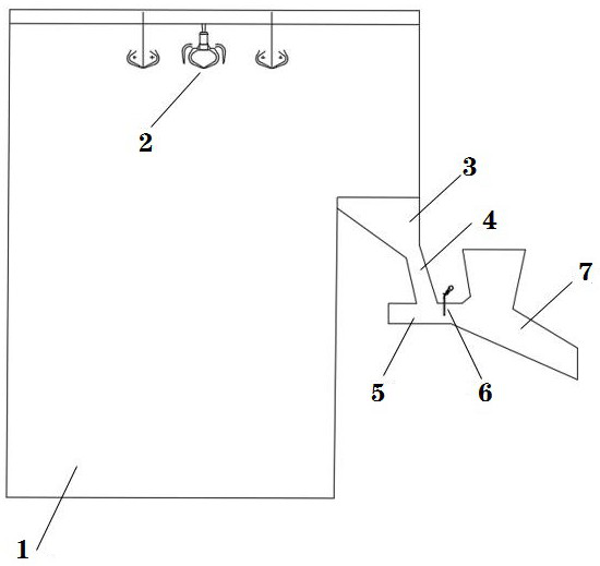
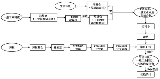
[0028] Such as figure 1 As shown, a feed system for co-incineration of domestic waste, general industrial solid waste and sludge. The feeding system includes a garbage bin 1 , a garbage grab 2 , a feeding hopper 3 , a chute 4 , a feeding grate 5 , a sludge feeding pipeline 6 and an incineration grate 7 . The garbage grab 2 is arranged on the top of the garbage bin 1, and is used for grabbing domestic garbage and general industrial solid waste. The top of the feeding hopper 3 communicates with the garbage bin 1, and the bottom communicates with the downwardly inclined chute 4, and the feeding grate 5 is installed at the bottom outlet of the chute 4. The sludge feeding pipeline 6 cancels the setting on the feeding hopper 3 and is installed above the feeding grate 5. The sludge directly falls on the surface of the garbage mixture of the feeding grate 5, preventing the sludge from accumulating in the chute 4 The phenomenon of agglomeration ensures the stability of combustion. T...
Embodiment 2
[0031] Such as image 3As shown, on the basis of Example 1, the sludge feed pipeline 6 includes a main pipeline 61 , a branch pipeline 62 , a valve 63 and a sludge dredging port 64 . The main pipeline 61 is connected to a sludge silo, and the sludge is pumped from the sludge silo to the main pipeline 61 through a plunger pump. The length direction of the main pipeline 61 is parallel to the width direction of the feeding grate 5 , and the branch pipelines 62 are evenly distributed between the main pipeline 61 and the feeding grate 5 , and are opened and closed by valves 63 . Specifically, the valve 63 can be a pneumatic ball valve. By controlling the pneumatic ball valves on the branch pipeline 62 to open and close in turn, only one pneumatic ball valve is opened at a time, so that the sludge is fed from the corresponding branch pipeline 62 to avoid opening multiple valves at the same time. A pneumatic ball valve causes uneven blanking of the corresponding branch pipeline 62. ...
PUM
 Abstract
Description
Claims
Application Information
 - R&D
- Intellectual Property
- Life Sciences
- Materials
- Tech Scout
- Unparalleled Data Quality
- Higher Quality Content
- 60% Fewer Hallucinations
Browse by: Latest US Patents, China's latest patents, Technical Efficacy Thesaurus, Application Domain, Technology Topic, Popular Technical Reports.
© 2025 PatSnap. All rights reserved.Legal|Privacy policy|Modern Slavery Act Transparency Statement|Sitemap|About US| Contact US: help@patsnap.com


