Machine head structure of punching machine

A punching machine and machine head technology, applied in the field of punching machines, can solve the problems of inability to adjust the position of the indenter to fix the punching position, errors, unstable punching position, etc., and achieve the effect of avoiding position errors and avoiding overheating and short circuits.

Active Publication Date: 2021-09-03
南阳浩帆车辆部件有限公司
View PDF5 Cites 2 Cited by
  • Summary
  • Abstract
  • Description
  • Claims
  • Application Information

AI Technical Summary

Problems solved by technology

[0003] While the punching machine is moving, the cylinder drives the pressure head to punch, so that the punching position is not stable, and the position of the pressure head cannot be reasonably adjusted and fixed while avoiding Stamping error occurred in the position

Method used


Image

  • Machine head structure of punching machine
  • Machine head structure of punching machine
  • Machine head structure of punching machine

Examples


Embodiment Construction

[0032] The following will clearly and completely describe the technical solutions in the embodiments of the present invention with reference to the accompanying drawings in the embodiments of the present invention. Obviously, the described embodiments are only some of the embodiments of the present invention, not all of them. Based on the embodiments of the present invention, all other embodiments obtained by persons of ordinary skill in the art without making creative efforts belong to the protection scope of the present invention.

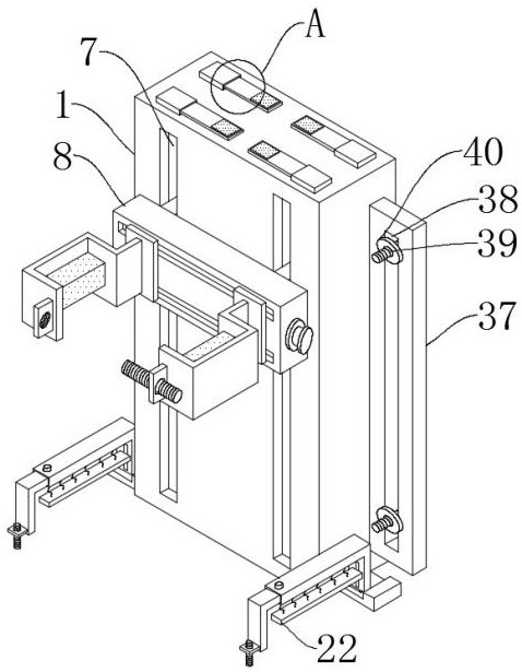
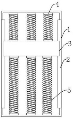
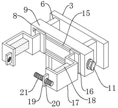
[0033] The present invention provides such Figure 1-11The shown head structure of a stamping machine includes a head base plate 1, first chute 2 is provided on both sides of the inner wall of the head base plate 1, and a buffer plate 3 is slidably connected inside the first chute 2, A first return spring 4 is fixedly connected between the top of the buffer plate 3 and the inner wall of the machine head bottom plate 1, and a second return spring ...


PUM


Abstract

The invention discloses a machine head structure of a punching machine. The machine head structure comprises a machine head bottom plate, first sliding grooves are formed in the two sides of the inner wall of the machine head bottom plate, and buffer plates are slidably connected into the first sliding grooves. By means of the machine head structure, a device is transferred to one side of a machine head, a limiting lead screw is used for being fixedly connected with the punching machine, when the connecting position deviates, the position can be adjusted at will, the machine head is placed between two stable clamping plates, the two stable clamping plates clamp the machine head, and an adjusting pad is attached and fixed according to the shape of the machine head; when stamping is conducted at the machine head, the buffer plates are driven to slide in the first sliding grooves and second sliding grooves through elastic force of a first reset spring and elastic force of a second reset spring to conduct buffer stamping, and the position of a pressing head is reasonably adjusted and fixed; and a movable clamping plate is rotated through a rotating shaft, and an adjusting clamping rod stably fixes a stamping base according to the elastic force of a third reset spring, so that the problem of stamping position errors is avoided.

Description

technical field [0001] The invention is used in the technical field of punching machines, and in particular relates to a head structure of a punching machine. Background technique [0002] The punching machine drives the flywheel through the motor, and through the clutch, the transmission gear drives the crank linkage mechanism to move the slider up and down, and drives the drawing die to form the steel plate. The so-called double action means that the press has two sliders, which are divided into an inner slider and an outer slider. The inner slider drives the punch or die of the mold, and the outer slider drives the blankholder on the mold. The blank holder first moves to press the edge of the steel plate, and then the inner slider moves to stretch. The design principle is to convert the circular motion into a linear motion. The main motor drives the flywheel, and the clutch drives the gear and crankshaft (or eccentric gear). , connecting rod, etc. to achieve the linear m...

Claims


Application Information

Patent Timeline
Patent Type & Authority Applications(China)
IPC IPC(8): B21D37/14
CPCB21D37/14
Inventor 虞丐良
Owner 南阳浩帆车辆部件有限公司
Why Eureka
Try Eureka