
Optical fiber test coupling device

A technology for coupling device and optical fiber testing, which is used in measurement devices, optical instrument testing, and optical performance testing. The effect of improving work efficiency

Pending Publication Date: 2021-08-31
JIANGDONG TECH CO LTD +2
View PDF6 Cites 0 Cited by
  • Summary
  • Abstract
  • Description
  • Claims
  • Application Information

AI Technical Summary

Problems solved by technology

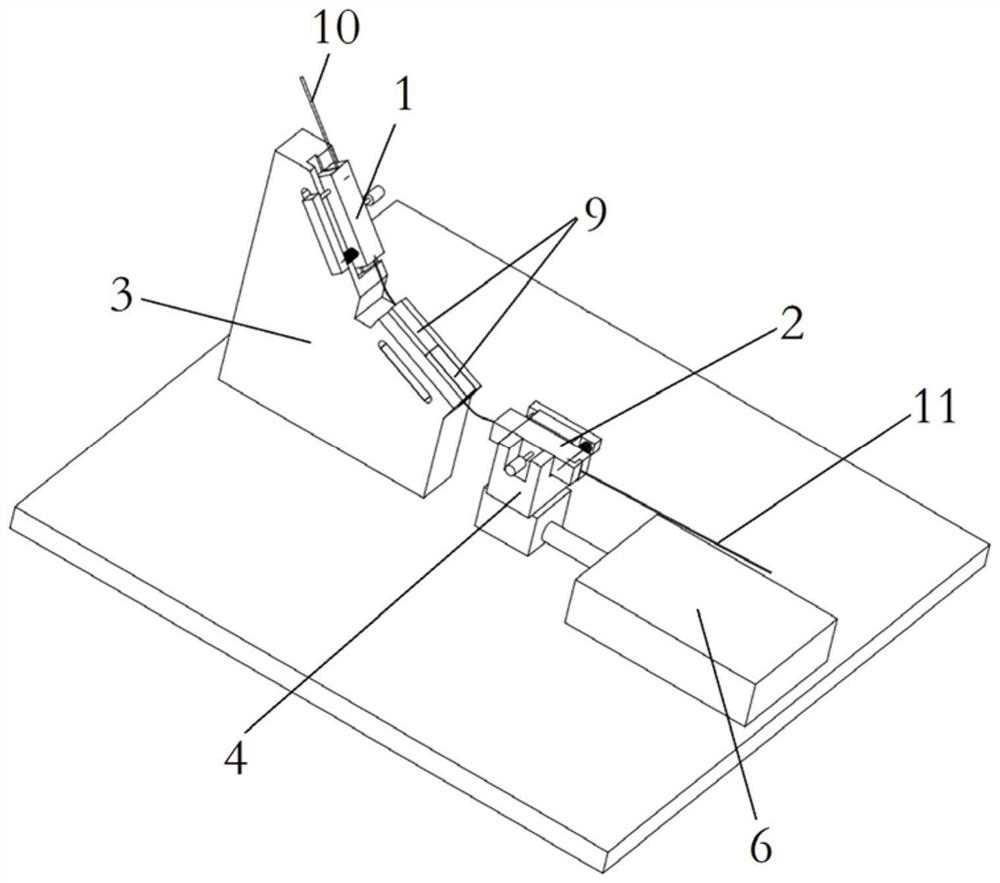
[0005] Therefore, the technical problem to be solved by the present invention is to overcome the defects that the coupling operation of the optical fiber in the prior art is manually performed by employees, the coupling operation is difficult and the efficiency is low, thereby providing a coupling device for optical fiber testing

Method used


Image

  • Optical fiber test coupling device
  • Optical fiber test coupling device
  • Optical fiber test coupling device

Examples


Embodiment Construction

[0047] The technical solutions of the present invention will be clearly and completely described below in conjunction with the accompanying drawings. Apparently, the described embodiments are some of the embodiments of the present invention, but not all of them. Based on the embodiments of the present invention, all other embodiments obtained by persons of ordinary skill in the art without making creative efforts belong to the protection scope of the present invention.

[0048] In the description of the present invention, it should be noted that the terms "center", "upper", "lower", "left", "right", "vertical", "horizontal", "inner", "outer" etc. The indicated orientation or positional relationship is based on the orientation or positional relationship shown in the drawings, and is only for the convenience of describing the present invention and simplifying the description, rather than indicating or implying that the referred device or element must have a specific orientation, ...


PUM


Abstract

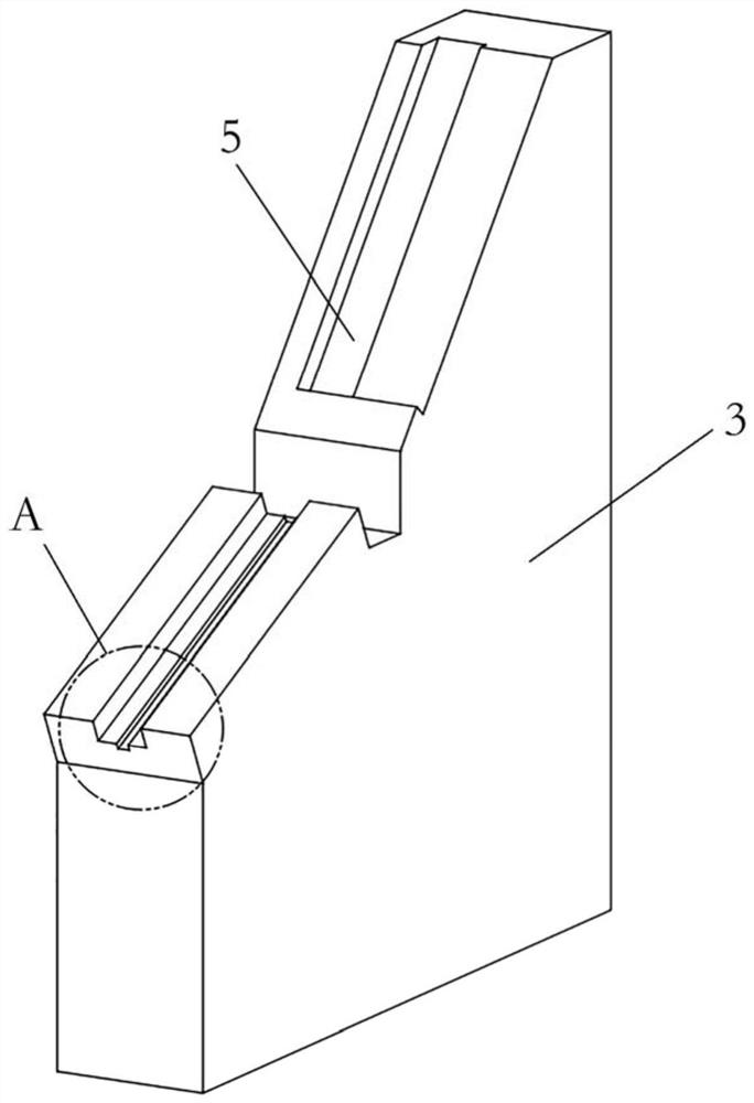
The invention provides an optical fiber test coupling device, and belongs to the technical field of optical fiber testing, and the device comprises a clamp, which is provided with a first clamp used for clamping a tail fiber and a second clamp used for clamping a to-be-tested optical fiber, wherein the first clamp and the second clamp are arranged in a relative movement manner; butt joint equipment that is arranged between the first clamp and the second clamp and is provided with a butt joint table top and a guide assembly located at the upper end of the butt joint table top. Compared with manual coupling operation of staff, the optical fiber test coupling device has the advantages that the working difficulty is reduced, and the working efficiency is improved.

Description

technical field [0001] The invention relates to the technical field of optical fiber testing, in particular to an optical fiber testing coupling device. Background technique [0002] With the rapid development of modern industry and the construction of informatization, our country maintains a vigorous growth momentum for optical fiber cables and optoelectronic devices. Therefore, the performance requirements for optical fibers are also increasing. [0003] During the optical fiber testing process, it is necessary to pass the coupling process so that the test optical signal passes through the test optical fiber. [0004] At present, the coupling operation of optical fibers is manually performed by employees, which is difficult and inefficient. Contents of the invention [0005] Therefore, the technical problem to be solved by the present invention is to overcome the defects in the prior art that the coupling operation of the optical fiber is manually performed by employees...

Claims


Application Information

Patent Timeline
IPC IPC(8): G01M11/02
CPCG01M11/0214Y02P40/57
Inventor 刘成阔朱刘盅吴磊季伟伟刘志忠
Owner JIANGDONG TECH CO LTD
Learn More